
Shaft hole coaxiality positioning assembly and positioning method using same

A technology for positioning components and positioning methods, applied in aircraft assembly and other directions, can solve the problems of accelerated wear, long time, and uneven force on rollers, and achieve the effects of reducing production complexity, reducing production costs, and increasing service life.

Active Publication Date: 2021-09-03
CHENGDU AIRCRAFT INDUSTRY GROUP
View PDF37 Cites 0 Cited by
  • Summary
  • Abstract
  • Description
  • Claims
  • Application Information

AI Technical Summary

Problems solved by technology

[0005] 1. Before installation, the measurement error of conventional measuring tools is relatively large, and various auxiliary tools need to be borrowed during the measurement process. The coaxiality of the shaft and the hole needs to be re-measured and calculated after each adjustment. The adjustment process is complicated and time-consuming, and the measurement accuracy cannot be obtained. Effective guarantee, low precision adjustment of shaft hole coaxiality
[0006] 2. During installation, it is easy to cause damage to bearings and components
Due to the low coaxiality of the shaft hole, when the bearing is installed, the inner rollers of the bearing are unevenly stressed, resulting in concentrated impact on the bearing rollers locally
At the same time, due to the uneven force on the contact surface between the bearing and the shaft or hole, the attitude of the bearing during installation is unstable, which may cause damage to the mating surface of the shaft or hole, resulting in a decrease in the accuracy of the part and scrapping
[0007] 3. After installation, the working stability and life of the bearing cannot be guaranteed
During the installation process, the operation lacks standardization, and the degree of bearing damage is uneven. Although some parts are not directly damaged, irregular damage has occurred inside the bearing, which will accelerate the wear during use and lead to a decrease in service life.

Method used


Image

  • Shaft hole coaxiality positioning assembly and positioning method using same
  • Shaft hole coaxiality positioning assembly and positioning method using same
  • Shaft hole coaxiality positioning assembly and positioning method using same

Examples


Embodiment 1

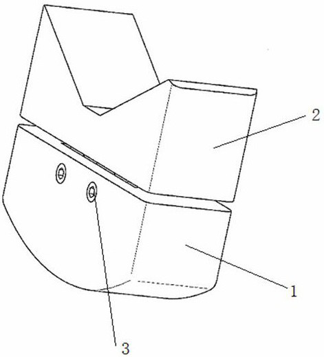
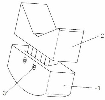
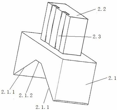
[0047] A shaft hole coaxiality positioning component belongs to the technical field of shaft hole installation in aircraft manufacturing. figure 1 , including a hole contact block 1 and a shaft contact block 2, one end of the hole contact block 1 is an arc surface structure 1.1; the other end of the hole contact block 1 is provided with a groove 1.2, and the side of the hole contact block 1 is provided with a fixing hole 1.3, so The arc surface structure 1.1 of the hole contact block 1 is used to contact the inner surface of the hole, and one end of the shaft contact block 2 is an angular positioning groove 2.1; the other end of the shaft contact block 2 is provided with a raised structure 2.2 matching the groove 1.2 , the angular positioning groove 2.1 is used to contact the outer surface of the shaft, the convex structure 2.2 of the shaft contact block 2 can slide in the groove 1.2, and pass the fixing hole 1.3 through the top screw 3 to the hole contact block 1 and The shaf...

Embodiment 2

[0053] This embodiment is a further optimization on Embodiment 1. It is a shaft hole coaxiality positioning assembly, which belongs to the technical field of shaft hole installation in aircraft manufacturing, and includes a hole contact block 1 and a shaft contact block 2. The hole contact block 1 One end is an arc surface structure 1.1; the other end of the hole contact block 1 is provided with a groove 1.2, and the side of the hole contact block 1 is provided with a fixing hole 1.3, and the arc surface structure 1.1 of the hole contact block 1 is used to contact the inner surface of the hole, One end of the shaft contact block 2 is an angular positioning groove 2.1; the other end of the shaft contact block 2 is provided with a raised structure 2.2 matching the groove 1.2, and the angular positioning groove 2.1 is used to contact the outer surface of the shaft. The protruding structure 2.2 of the contact block 2 can slide in the groove 1.2, and fix the hole contact block 1 and...

Embodiment 3

[0056] Compared with Embodiment 1-2, this embodiment differs in that the protrusion structure 2.2 of the shaft contact block 2 is a trapezoidal protrusion 2.2.1 matching the trapezoidal groove 1.2.1, refer to Figure 4 , the angular positioning groove 2.1 and the trapezoidal protrusion 2.2.1 on the shaft contact block 2 are both axisymmetric structures.


PUM


Abstract

The invention discloses a shaft hole coaxiality positioning assembly and a positioning method of the positioning assembly, and belongs to the technical field of shaft hole installation in aircraft manufacturing, the positioning assembly comprises a hole contact block and a shaft contact block, and one end of the hole contact block is of a cambered surface structure; a groove is formed in the other end of the hole contact block, a fixing hole is formed in the side face of the hole contact block, the cambered surface structure of the hole contact block is used for making contact with the inner surface of a hole, and an angle positioning groove is formed in one end of the shaft contact block; the other end of the shaft contact block is provided with a protruding structure matched with the groove, the angle positioning groove is used for making contact with the outer surface of a shaft, the protruding structure of the shaft contact block can slide in the groove, and a jackscrew penetrates through the fixing hole to fix the hole contact block and the shaft contact block. The shaft hole coaxiality positioning assembly settles a problem that in shaft hole mounting in prior art, the center of a shaft and the center of a hole cannot be on the same line and the mounting accuracy is low, and the service life of a machine tool can be remarkably prolonged.

Description

technical field [0001] The invention relates to the technical field of shaft hole installation in aircraft manufacturing, in particular to a shaft hole coaxiality positioning component and a positioning method using the positioning component. Background technique [0002] In the field of aircraft manufacturing, compared with other ordinary machinery manufacturing fields, there are higher requirements for manufacturing accuracy and reliability. In the machining equipment-machine tool, the whole machine is composed of various functional components, and the functional components are assembled from parts. The factors that affect the running stability of components mainly include two parts: parts manufacturing precision and assembly precision. [0003] Among them, bearings are widely used as rotating positioning components. The installation accuracy of bearings is generally guaranteed by special tooling. General-purpose tools are limited by space and cannot be measured and tested...

Claims


Application Information

Patent Timeline
Patent Type & Authority Applications(China)
IPC IPC(8): B64F5/10
CPCB64F5/10
Inventor 潘世禄董光亮贾永锋赵国波李颖王强军张云贺毅蒋云峰符垚慧梅赵长永宋智勇
Owner CHENGDU AIRCRAFT INDUSTRY GROUP
Learn More