Interior wall coating spraying equipment for interior decoration
A technology of interior wall paint and spraying equipment, which is applied in the direction of architecture and building structure, which can solve the problems of easy falling and labor-consuming for users, and achieve the effects of ensuring safety, improving painting effect and simple operation
- Summary
- Abstract
- Description
- Claims
- Application Information
AI Technical Summary
Problems solved by technology
Method used
Image

Examples
Embodiment 1
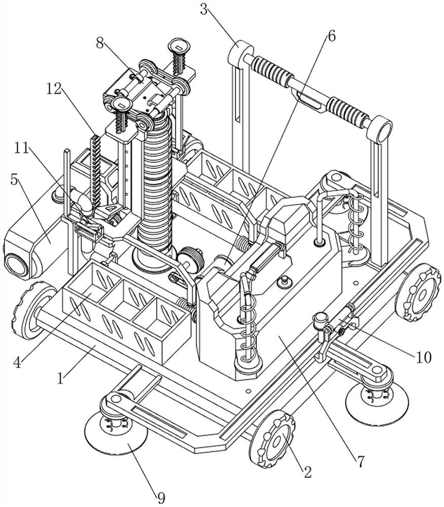
[0040] A kind of interior wall paint spraying equipment for indoor decoration, such as Figure 1-7As shown, it includes a support plate 1, a tire 2, a handrail 3, a discharge frame 4, a sponge brush 5, a motor 6, a paint mechanism 7 and a lifting mechanism 8, and the left and right sides of the support plate 1 are rotatably connected with two tires 2. , the two tires 2 are symmetrical front and back, the top and rear side of the support plate 1 is connected with the handrail 3, the front and rear sides of the top of the support plate 1 are connected with the discharge frame 4, the motor 6 is installed in the middle of the top of the support plate 1, and the top of the support plate 1 is provided with The coating mechanism 7 is provided with a sponge brush 5, and a lifting mechanism 8 is arranged between the motor 6, the support plate 1 and the coating mechanism 7.
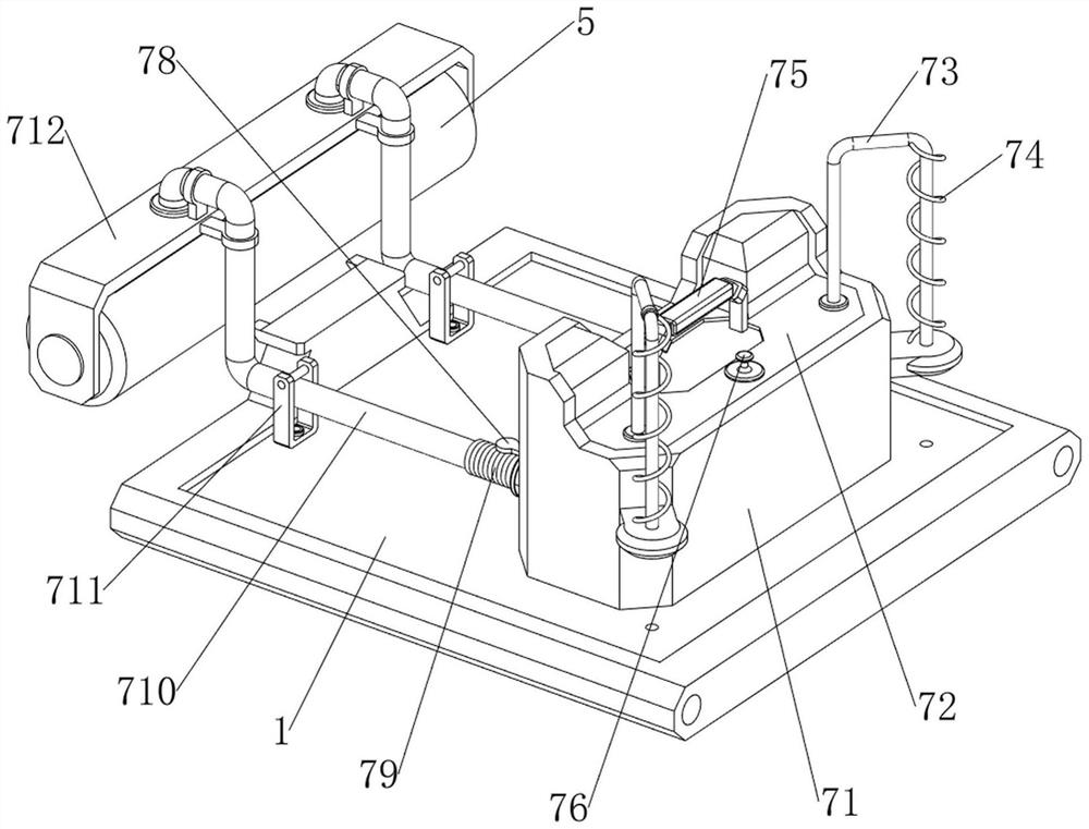
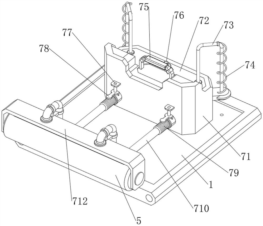
[0041] The paint mechanism 7 includes a charging bucket 71, a pressing plate 72, a first connecting rod 73, a fi...
Embodiment 2
[0046] On the basis of Example 1, such as figure 1 , Figure 8 and Figure 9 As shown, a stabilizing mechanism 9 is also included. The stabilizing mechanism 9 includes a second connecting plate 91, a suction cup 92 and a third spring 93. The middle part of the front and rear sides of the support plate 1 and the middle part of the right side are connected with the second connecting plate 91. A suction cup 92 is slidably connected to the second connection plate 91 , and four third springs 93 are connected between the suction cup 92 and the second connection plate 91 .
[0047] When spraying, the suction cup 92 can be pressed on the ground, thereby fixing the whole device, and avoiding that the device moves to affect the spraying when spraying. Spring 93 is compressed, and like this, just can fix whole device when spraying, avoid device displacement to affect spraying when spraying.
[0048] Such as figure 1 , Figure 10 and Figure 11 As shown, a buckle mechanism 10 is als...
Embodiment 3
[0051] On the basis of Example 2, such as figure 1 , Figure 12 , Figure 13 and Figure 14 As shown, a complementary mechanism 11 is also included, and the complementary mechanism 11 includes a top plate 111, a fourth spring 112, a wedge block 113, a fixed plate 1141, a guide plate 1142, a push rod 115, a fifth spring 116, and a fourth connecting rod 117 , the sixth spring 118, the fifth connecting rod 119 and the seventh spring 1110, the top plate 111 is slidably connected to the front and rear sides of the first connecting plate 89, and two top plates 111 are connected to the first connecting plate 89. The fourth spring 112, the two fourth springs 112 are symmetrical front and rear, the top plate 111 bottom is connected with a wedge block 113, the second connecting rod 87 and the first connecting plate 89 are connected with a fixed plate 1141, and the front and rear sides of the fixed plate 1141 are connected There is a guide plate 1142, the guide plate 1142 is slidably ...
PUM
 Abstract
Description
Claims
Application Information
 - R&D Engineer
- R&D Manager
- IP Professional
- Industry Leading Data Capabilities
- Powerful AI technology
- Patent DNA Extraction
Browse by: Latest US Patents, China's latest patents, Technical Efficacy Thesaurus, Application Domain, Technology Topic.
© 2024 PatSnap. All rights reserved.Legal|Privacy policy|Modern Slavery Act Transparency Statement|Sitemap