
A Perforated Yield Energy Dissipator

A technology of energy consumers and connecting holes, which is applied in the direction of shock absorbers, shock absorbers, springs/shock absorbers, etc., can solve the problems of inconvenient installation and replacement, complex structure, etc., and achieve convenient disassembly and maintenance and low energy consumption. Mechanism is clear and the effect of improving energy consumption capacity

Active Publication Date: 2022-06-17
SOUTHWEST JIAOTONG UNIV
View PDF12 Cites 0 Cited by
  • Summary
  • Abstract
  • Description
  • Claims
  • Application Information

AI Technical Summary

Problems solved by technology

The energy dissipation capacity of the deformable energy dissipation device has been improved, but due to the complex structure, installation and replacement are very inconvenient, and it is difficult to optimize on the basis of the existing structure to greatly improve its energy dissipation capacity

Method used


Image

  • A Perforated Yield Energy Dissipator
  • A Perforated Yield Energy Dissipator
  • A Perforated Yield Energy Dissipator

Examples


Embodiment 1

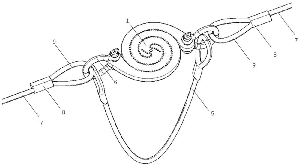
[0063] like figure 2 Shown, a design method for a perforated yield-type energy dissipator. When used alone, the energy dissipator includes a metal plate 1 with a hole, a protection rope 5 and two shackles 6 .

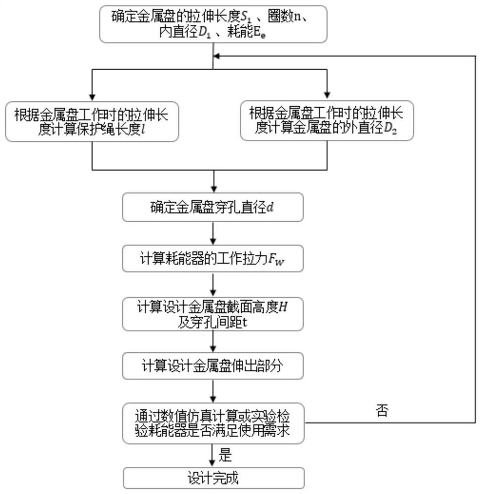
[0064] according to figure 1 The design flow shown is for computational design:

[0065] Determine the stretched length, the number of spiral turns, and the inner diameter of the metal disc when it is working: According to the allowable slippage length and space of the wire rope in the flexible protection system connected in this embodiment, the stretched length S of the energy dissipator in this embodiment is 1 is 1500mm, the helix number n of the single arm of the metal disc is 1.5, and the inner diameter D 1 is 80mm;

[0066] Calculate the length of the protection rope according to the tensile length of the metal disc when it is working: according to the formula l=1.1S 1 Calculate the length of the protective rope, the stretched length S of the metal plate 1 =...

Embodiment 2

[0079] like Figure 7 , Figure 8 Shown, a design method for a perforated yield-type energy dissipator. The energy dissipator includes four metal discs 1 with holes and one connecting bolt 10 when used in parallel and combined according to this embodiment.

[0080] like Figure 9 As shown, when the energy dissipator is used in parallel and in combination according to this embodiment, according to the practice in Embodiment 1, four metal discs with holes 1 are connected in parallel through bolts 10 to form the main structure.

[0081] The main structure of the energy dissipator ( Figure 9 ) by connecting the structure ( Figure 4 ) is connected with the wire rope of the flexible protection system to form Figure 7 , Figure 8 The complete structure of the energy dissipator when used in combination according to this embodiment is shown.

[0082] When the flexible protection system is impacted, the wire rope is pulled, and the 4 metal discs are simultaneously pulled from...

Embodiment 3

[0084] like Figure 10 Shown, a design method for a perforated yield-type energy dissipator. According to this embodiment, the energy dissipator includes two metal disks 1 with holes and one "8"-shaped steel cable 11 when used in series.

[0085] The main structure of the energy dissipator ( image 3 ) is connected by an "8"-shaped steel cable, and then connected with the flexible protection system steel cable, thereby forming a Figure 10 The complete structure of the energy dissipator when used in series according to this embodiment is shown.

[0086] When the energy dissipators are used in series according to this embodiment, the maximum slippage of the wire rope of the flexible protection system can be increased by 2 times.


PUM


Abstract

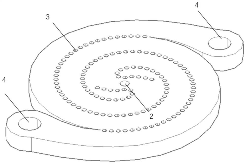
This application relates to a design method for a perforated yield energy dissipator, which includes a metal disc with holes, a clamp, a protection rope and a connection structure. The metal disc has small holes in a spiral distribution to form a preset tear path. Holes are reserved at both ends for detachable connection with the steel wire rope of the flexible protection system, and the protection rope is connected to the steel wire rope through a connection structure. When the flexible protection system is impacted, the metal disk is torn along the perforation path, forming two tensile arms, which extend in opposite directions, and achieve the purpose of cushioning and energy dissipation through the yield deformation of the steel. The invention combines the deformation and brittle braking performance of steel with the modularized energy dissipator, the number of energy dissipators can be designed and assembled according to the actual energy consumption demand, and the components in the slope flexible protection system can be optimized by adjusting the characteristic response curve interaction between. The energy consumption device of the invention has reasonable design, clear energy consumption mechanism, can be used in combination, and effectively improves the energy consumption capacity of the protection system.

Description

technical field [0001] The invention relates to a design method of a perforated yield-type energy dissipator, belonging to the field of slope geological disaster protection. Background technique [0002] As modern infrastructure, transportation facilities and mountain scenic spots face increasing threats from disasters such as collapse, rockfall, landslide, and debris flow, flexible protection systems have gradually developed into one of the most effective protection measures. The flexible protection system consists of a support column, a flexible metal interception net, an energy dissipator, and an anchor system. When the protection system is impacted, the mesh ring is deformed, the anchor system is tensioned, and the energy dissipator works to dissipate the impact energy and prolong the impact time. and reduce the impact force. In the early days of rockfall protection systems, friction-type energy dissipation devices were used, which were assembled by wire ropes through r...

Claims


Application Information

Patent Timeline
Patent Type & Authority Patents(China)
IPC IPC(8): F16F7/00E01F7/04
CPCF16F7/00E01F7/045
Inventor 齐欣余志祥郝超然赵雷许浒
Owner SOUTHWEST JIAOTONG UNIV
Learn More