Display screen, manufacturing method thereof and electronic equipment with display screen

A production method and technology of electronic equipment, applied in branch office equipment, television, telephone communication, etc., can solve the problems of large through-hole area of ​​camera and small screen-to-body ratio, so as to ensure imaging quality, reduce area, and increase screen-to-body ratio Effect

Pending Publication Date: 2021-09-03
SHENZHEN CHINA STAR OPTOELECTRONICS SEMICON DISPLAY TECH CO LTD
View PDF5 Cites 0 Cited by
  • Summary
  • Abstract
  • Description
  • Claims
  • Application Information

AI Technical Summary

Problems solved by technology

[0005] In view of this, the present application provides a display screen, which aims to solve the problem of a small screen-to-body ratio caused by the large area of ​​the camera through hole of the existing display screen

Method used


Image

  • Display screen, manufacturing method thereof and electronic equipment with display screen
  • Display screen, manufacturing method thereof and electronic equipment with display screen
  • Display screen, manufacturing method thereof and electronic equipment with display screen

Examples


Embodiment 1

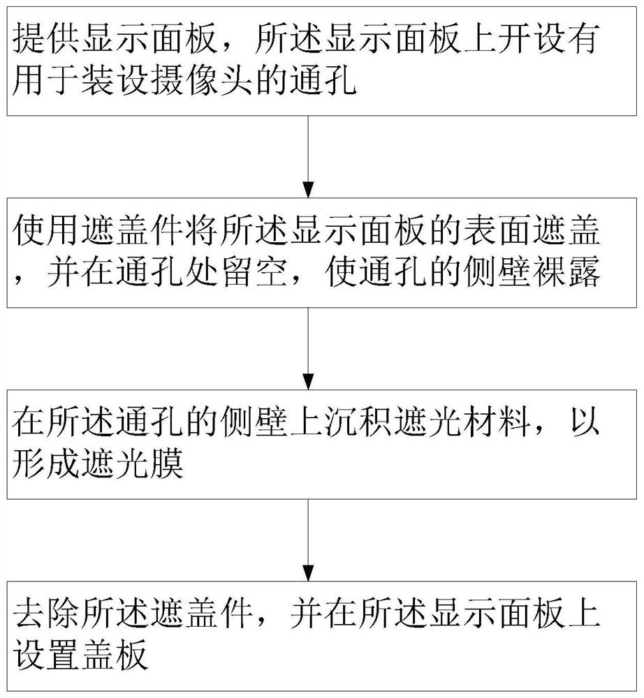
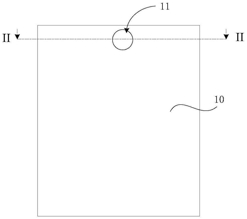
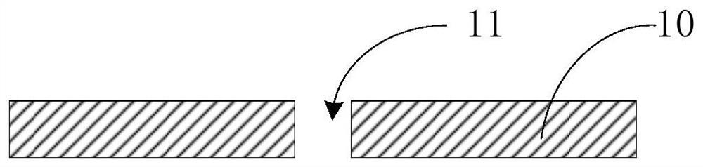
[0058] A display panel 10 is provided, and the display panel 10 is provided with a through hole 11 for installing a camera;

[0059] Covering the surface of the display panel 10 with a mask plate, and leaving a hole at the through hole 11, so that the side wall of the through hole 11 is exposed;

[0060] On the side wall of the through hole 11, the light-shielding material Ti is deposited by PVD sputtering coating method to form a layer with a thickness of The light-shielding film 20, wherein the sputtering target is a Ti target, the power is 10w, the air pressure is 0.3Pa, and the temperature is 25°C;

[0061] The reticle is removed, and a glass cover 30 is disposed on the display panel 10 .

Embodiment 2

[0063] A display panel 10 is provided, and the display panel 10 is provided with a through hole 11 for installing a camera;

[0064] Covering the surface of the display panel 10 with a mask plate, and leaving a hole at the through hole 11, so that the side wall of the through hole 11 is exposed;

[0065] On the side wall of the through hole 11, the light-shielding material W is deposited by PVD sputtering coating method to form a layer with a thickness of The light-shielding film 20, wherein the sputtering target is a W target, the power is 50w, the air pressure is 2.0Pa, and the temperature is 25°C;

[0066] On the surface of the light-shielding film 20 away from the display panel 10, a molybdenum antireflection film 40 with an oxidation thickness of 50 nm is deposited by PVD sputtering coating method, wherein the sputtering target is a molybdenum oxide target, the power is 500w, and the air pressure is 2.0Pa. Temperature 25°C;

[0067] The reticle is removed, and a glass ...

Embodiment 3

[0069] A display panel 10 is provided, and the display panel 10 is provided with a through hole 11 for installing a camera;

[0070] Covering the surface of the display panel 10 with a mask plate, and leaving a hole at the through hole 11, so that the side wall of the through hole 11 is exposed;

[0071] On the side wall of the through hole 11, the light-shielding material MoNb is deposited by PVD sputtering coating method to form a thickness of The light-shielding film 20, wherein the sputtering target is a MoNb target, the power is 50w, the air pressure is 2.0Pa, and the temperature is 25°C;

[0072] The reticle is removed, and a glass cover 30 is disposed on the display panel 10 .


PUM


Abstract

The invention discloses a display screen which comprises a display panel and a cover plate covering the surface of the display panel, a through hole used for installing a camera is formed in the display panel, and at least one layer of shading film is deposited on the side wall of the through hole. According to the display screen, the shading film is deposited on the side wall of the through hole used for installing the camera, and the shading film can prevent the light in the display panel from entering the through hole through the side wall of the through hole, so that the light in the display panel is prevented from influencing the imaging effect of the camera in the through hole, and the imaging quality of the camera can be effectively guaranteed. Besides, the shading film is deposited on the side wall of the through hole used for installing the camera through a deposition method, so that the thickness of the shading film can be accurately controlled, it is guaranteed that the shading film has a small thickness, the through hole has a small area, and the screen-to-body ratio can be increased. In addition, the invention further discloses a manufacturing method of the display screen and electronic equipment using the display screen.

Description

technical field [0001] The present application relates to the field of display technology, and in particular to a display screen, a manufacturing method of the display screen, and an electronic device having the display screen. Background technique [0002] With the development of science and technology, people have higher and higher requirements for the display screens of electronic devices such as mobile phones, TVs, computers, smart watches, etc., so full screens gradually appear on electronic devices. On the one hand, the full screen can make the electronic device more visually beautiful and bring users a better visual experience; on the other hand, it can reduce the area of ​​the electronic device so that it can have a larger display panel with the same size. [0003] However, the full-screen electronic device also has some disadvantages. While the full-screen electronic device increases the proportion of the display panel as much as possible, it will bring some technic...

Claims


Application Information

Patent Timeline
Patent Type & Authority Applications(China)
IPC IPC(8): H04M1/02H04N5/225
CPCH04M1/0266H04M1/0264H04N23/57
Inventor 胡小波
Owner SHENZHEN CHINA STAR OPTOELECTRONICS SEMICON DISPLAY TECH CO LTD
Why Eureka
Try Eureka