Surgical instrument disinfection treatment and recovery equipment
A recycling equipment and surgery technology, which is applied in the field of sterilization treatment and recycling equipment for surgical and surgical instruments, and can solve problems such as poor economy and the like
- Summary
- Abstract
- Description
- Claims
- Application Information
AI Technical Summary
Problems solved by technology
Method used
Image
Examples
specific Embodiment approach 1
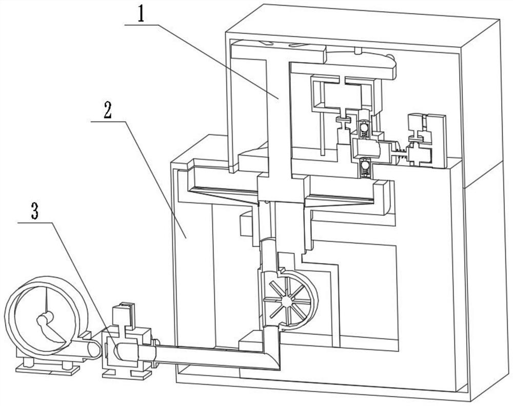
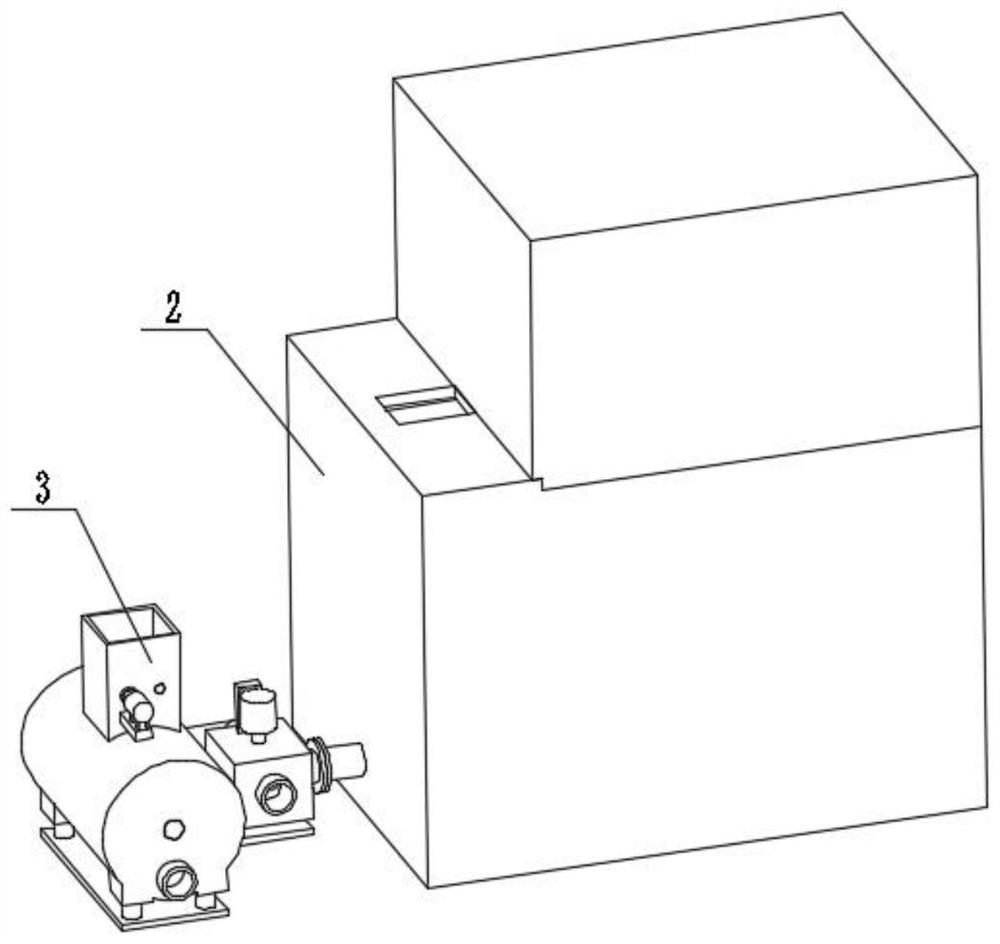
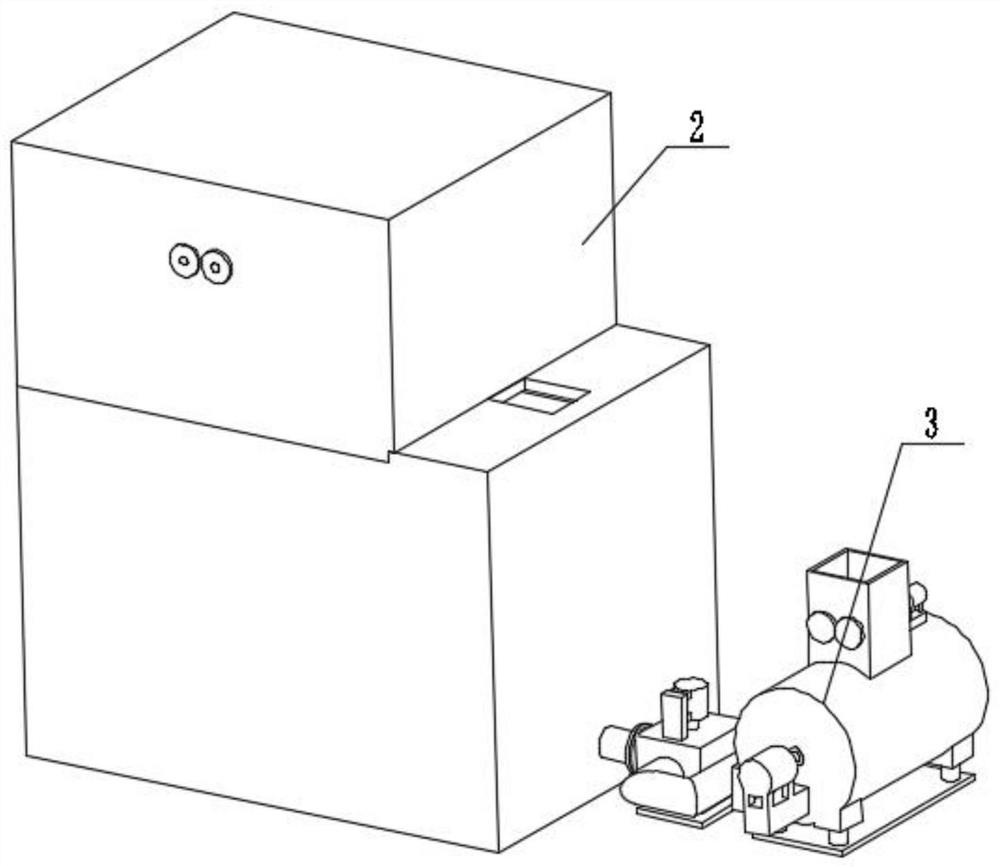
[0032] Combine below figure 1 , figure 2 , image 3 , Figure 4 , Figure 5 , Figure 6 , Figure 7 , Figure 8 , Figure 9 , Figure 10 , Figure 11 , Figure 12 , Figure 13 , Figure 14 , Figure 15 To illustrate this embodiment, the present invention relates to a disinfection device, more specifically, a device for disinfection treatment and recovery of surgical instruments, including a disinfection mechanism 1, a box body mechanism 2, and a garbage disposal mechanism 3, and the equipment can guarantee the spraying of disinfectant , the equipment can ensure that the sprayed disinfectant is uniform, the equipment can choose the purpose of discharging the waste liquid, and the equipment can handle medical waste.
[0033] The disinfection mechanism 1 is connected with the box mechanism 2 , and the disinfection mechanism 1 is connected with the garbage disposal mechanism 3 .
specific Embodiment approach 2
[0035] Combine below figure 1 , figure 2 , image 3 , Figure 4 , Figure 5 , Figure 6 , Figure 7 , Figure 8 , Figure 9 , Figure 10 , Figure 11 , Figure 12 , Figure 13 , Figure 14 , Figure 15 Describe this embodiment, this embodiment will further explain the first embodiment, the disinfection mechanism 1 includes an output pipe 1-1, a rotating support base 1-2, a motor 1-3, a coupling 1-4, and a bellows 1- 5. Connecting pipe 1-6, rotating disinfection seat 1-7, soaking chamber 1-8, chute 1-9, rotating shaft 1-10, passive disk 1-11, passive groove 1-12, inlet pipe 1-13, With raised plate 1-14, mixing box 1-15, cam drive motor 1-16, motor seat 1-17, coupling I1-18, pressure change tube 1-19, piston rod 1-20, spring 1- 21. Cooperating seat 1-22, cam with shaft 1-23, transfer box 1-24, motor I1-25, auxiliary support 1-26, coupling II1-27, stirring wheel with shaft 1-28, liquid inlet unit Directional valve 1-29, piston 1-30, liquid outlet one-way valve 1-3...
specific Embodiment approach 3
[0037] Combine below figure 1 , figure 2 , image 3 , Figure 4 , Figure 5 , Figure 6 , Figure 7 , Figure 8 , Figure 9 , Figure 10 , Figure 11 , Figure 12 , Figure 13 , Figure 14 , Figure 15 This embodiment will be described. This embodiment will further describe the first embodiment. The box mechanism 2 includes an opening I2-1, a lower box 2-2, an insertion port 2-3, an upper box 2-4, The opening II2-5, the opening I2-1 is arranged on the lower box body 2-2, the insertion port 2-3 is arranged on the lower box body 2-2, the upper box body 2-4 is connected with the lower box body 2-2, The opening II2-5 is set on the upper box body 2-4, the rotating support seat 1-2 is connected with the lower box body 2-2, the inlet pipe 1-13 is set in the opening II2-5, and the output pipe 1-1 is set Inside the opening I2-1.
PUM
 Abstract
Description
Claims
Application Information
 - R&D
- Intellectual Property
- Life Sciences
- Materials
- Tech Scout
- Unparalleled Data Quality
- Higher Quality Content
- 60% Fewer Hallucinations
Browse by: Latest US Patents, China's latest patents, Technical Efficacy Thesaurus, Application Domain, Technology Topic, Popular Technical Reports.
© 2025 PatSnap. All rights reserved.Legal|Privacy policy|Modern Slavery Act Transparency Statement|Sitemap|About US| Contact US: help@patsnap.com


