Sputum suction device capable of reducing vacuum residues and manufacturing process

A vacuum and air cavity technology, applied in the field of medical equipment, can solve the problems of respiratory skin rupture, large vacuum residual value, and difficult vacuum residual value.

Pending Publication Date: 2021-09-07
江苏邦盛振业医疗器械有限公司
View PDF0 Cites 0 Cited by
  • Summary
  • Abstract
  • Description
  • Claims
  • Application Information

AI Technical Summary

Problems solved by technology

[0004] However, in the above-mentioned prior art, when using the sputum suction tube (1) to suck sputum, there are problems that the vacuum residual value is large and the vacuum residual value is not easy to control to meet the requirements of the specification. According to the provisions of the industry standard YY0339, the sputum suction tube (1 ) should be less than 0.33kpa, if the vacuum residue of the sputum suction tube (1) is greater than 0.33kpa, the patient's airway epidermis may be ruptured, causing damage to the patient's airway epidermis

Method used


Image

  • Sputum suction device capable of reducing vacuum residues and manufacturing process
  • Sputum suction device capable of reducing vacuum residues and manufacturing process
  • Sputum suction device capable of reducing vacuum residues and manufacturing process

Examples


Embodiment 1

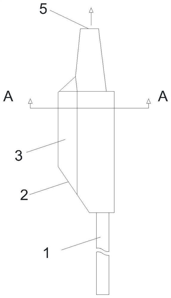
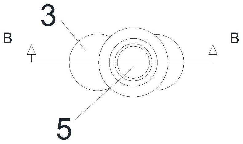
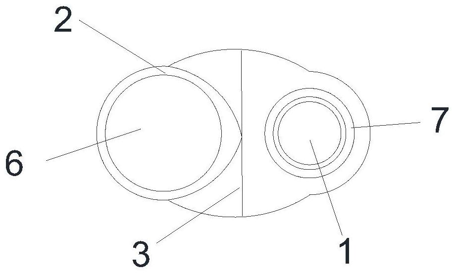
[0051] Such as Figure 6-12As shown, the present invention provides a sputum suction device that reduces vacuum residue, comprising a body 3 made of ABS material, the ABS material is a heat-melt polypropylene material, a negative pressure port 5 and a negative pressure tube on the body 3 The airtight connection, the negative pressure tube is connected with the external negative pressure equipment to provide a negative pressure source for the patient to suck sputum. The third air chamber 8, the first air chamber 6 and the third air chamber 8 are arranged in parallel, the third air chamber 8 is a linear shape connected at both ends, one end of the third air chamber 8 is a negative pressure port 5, and The other end of 8 is obliquely provided with manual control port 2. In this embodiment, in order to reduce resistance, the negative pressure port 5 and the manual control port 2 are straight cylindrical structures arranged on the same straight line. Wherein, the blind ends of th...

Embodiment 2

[0058] This embodiment has been improved on the basis of Embodiment 1, and other structures are the same, the difference is: as Figure 15-18 As shown, the present embodiment provides a suction device for reducing vacuum residue, the valve 9 is set as a sealing plate 91 made of hard material, and the sealing plate 91 is a baffle structure, and the baffle structure is specifically the The bottom is provided with a rotating part 11 , and the rotating part 11 rotates around an axis 13 .

[0059] In this embodiment, the bottom of the baffle of the sealing plate 91 structure is provided with a transverse baffle 95, and an included angle b is set between the baffle of the sealing plate 91 and the transverse baffle 95, and the angle range of the included angle b is 0°


PUM

PropertyMeasurementUnit
thicknessaaaaaaaaaa
thicknessaaaaaaaaaa

Abstract

The invention belongs to the technical field of medical instruments, and particularly relates to a sputum suction device capable of reducing vacuum residues and a manufacturing process. The sputum suction device capable of reducing the vacuum residues comprises a negative pressure pipe which is in closed connection with a negative pressure opening in a body, a sputum suction opening of the body is in closed connection with a sputum suction pipe, a first air cavity and a third air cavity are formed in the body, the negative pressure opening is formed in one end of the third air cavity, a manual control port is formed in the other end of the third air cavity, the blind end of the first air cavity and the middle of the third air cavity communicate with each other and are converged, and valves which communicate with each other and are closed at any time are arranged on the first air cavity and the third air cavity. The sputum suction device is simple in structure, convenient to operate and stable in performance, and the purpose of protecting the respiratory tract of a patient from being hurt is effectively achieved. It can be completely guaranteed that the vacuum residues of the sputum suction pipe are smaller than 0.33 kpa, and the purpose that the vacuum residues are close to zero is achieved.

Description

technical field [0001] The invention belongs to the technical field of medical equipment, and in particular relates to a sputum suction device and a manufacturing process for reducing vacuum residue. Background technique [0002] Sputum suction is a treatment method of forced sputum suction after routine suction, tracheal intubation or tracheotomy for the wounded and sick. In hospital treatment, patients with pneumonia and bronchitis are more common. The trachea of ​​the patient is often blocked by sputum. If it is not removed in time, it will affect the patient's normal breathing, and in severe cases, it will cause life-threatening. [0003] Such as Figure 1-5 As shown, the sputum suction device currently used in the prior art includes a body (3) that controls the patient to suck sputum. The body (3) is internally provided with a first air chamber (6), a second air chamber (7) and a third air chamber. The air chamber (8), the first air chamber (6) and the second air chamb...

Claims


Application Information

Patent Timeline
Patent Type & Authority Applications(China)
IPC IPC(8): A61M1/00B29C45/14B29C45/78
CPCB29C45/14B29C45/78B29C2945/76531
Inventor 张冰
Owner 江苏邦盛振业医疗器械有限公司
Why Eureka
Try Eureka