Biological test tube cleaning device

A technology for cleaning devices and test tubes, which is applied in the direction of cleaning hollow objects, cleaning methods and utensils, chemical instruments and methods, etc., and can solve problems such as laborious work, low work efficiency, and decreased work enthusiasm

Pending Publication Date: 2021-09-07
张佩
View PDF5 Cites 0 Cited by
  • Summary
  • Abstract
  • Description
  • Claims
  • Application Information

AI Technical Summary

Problems solved by technology

[0004] In order to overcome the shortcoming that people need to keep moving, it takes a long time, it is laborious, the work efficiency is low, and only one test tube can be cleaned at a time, which leads to the decline of people's work enthusia

Method used


Image

  • Biological test tube cleaning device
  • Biological test tube cleaning device
  • Biological test tube cleaning device

Examples


Embodiment 1

[0028] A biological test tube cleaning device, such as figure 1 , figure 2 , image 3 , Figure 4 and Figure 8 As shown, it includes a base 1, a slotted fixing frame 2, a driving mechanism 3 and a cleaning mechanism 4. The left side of the top of the base 1 is symmetrically fixed with a slotted fixing frame 2. A cleaning mechanism 4 is provided on the frame 2, and the cleaning mechanism 4 contacts and cooperates with the driving mechanism 3.

[0029] The driving mechanism 3 includes a first fixed block 31, a cylinder 32, a second fixed block 33, a push rod 34 and a sliding block 35. A cylinder 32 is provided, and a second fixed block 33 is affixed to the ends of the telescopic rods of the cylinders 32 on the front and rear sides, and a push rod 34 is affixed symmetrically to the front and back of the left side of the second fixed block 33. A sliding block 35 is fixedly connected between them.

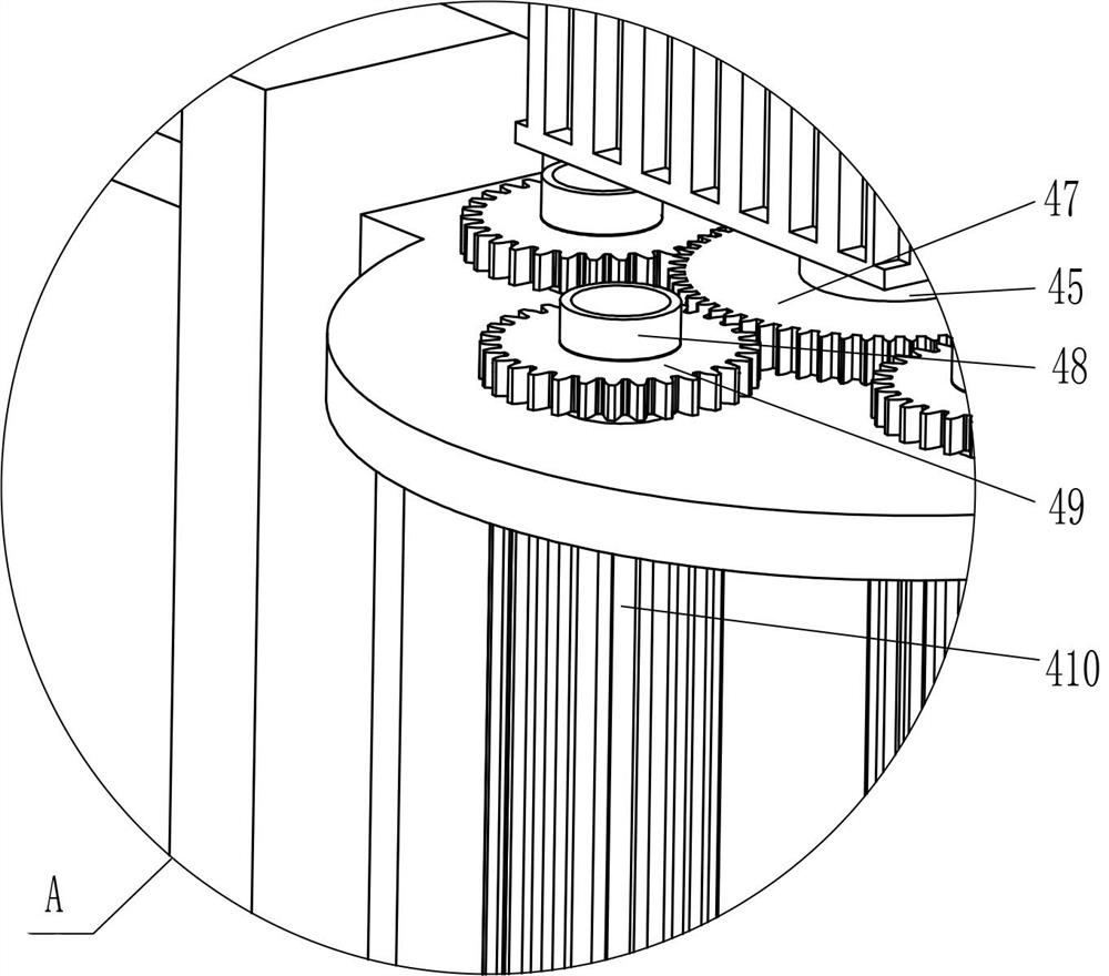
[0030] The cleaning mechanism 4 includes a slide plate 41, a slide bar 42, ...

Embodiment 2

[0033] On the basis of Example 1, such as figure 1 , figure 2 , Figure 5 and Image 6 As shown, a clamping and positioning mechanism 5 is also included. The clamping and positioning mechanism 5 includes a first limit block 51, an L-shaped fixed block 52, a first spring 53, a fourth fixed block 54 and a guide wheel 55. The top of the base 1 The middle is affixed with the first stopper 51, and the front and rear sides of the first stopper 51 middle part are all affixed with the L-shaped fixed block 52, and the inner side of the L-shaped fixed block 52 is symmetrically affixed with the first spring 53. A fourth fixed block 54 is fixedly connected between the tail ends of the first springs 53 on the side, and the fourth fixed block 54 is provided with guide wheels 55 in a left and right symmetrical rotation.

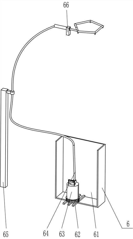
[0034]Also includes a delivery mechanism 6, the delivery mechanism 6 includes a water storage frame 61, the fifth fixed block 62, a water pump 63, a hose 64, the sixth ...

Embodiment 3

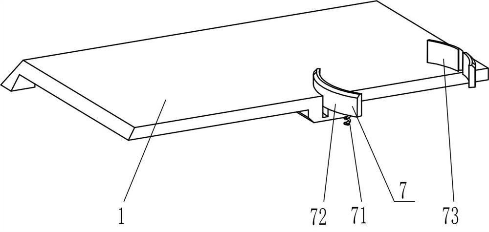
[0038] On the basis of embodiment 1 and embodiment 2, such as figure 1 , figure 2 and Figure 7 As shown, a fixing device 7 is also included. The fixing device 7 includes a second spring 71, a second limiting block 72 and an eighth fixing block 73. The left part of the base 1 is slidably provided with a second limiting block 72, and the second The bottom of the limiting block 72 and the inside of the base 1 are fixed with a second spring 71 symmetrically front and back, and the middle of the top of the base 1 is fixed with an eighth fixing block 73 .

[0039] When the test tube rack is placed under the cleaning rod 410, the test tube rack is in contact with the second stopper 72, and due to the action of the second spring 71, the test tube rack slides over the second stopper 72, and then the second stopper 72 Cooperate with the eighth fixed block 73 to limit the test tube. When the test tube is cleaned, press the second limit block 72 to move downward, the second spring 71 ...


PUM


Abstract

The invention relates to a cleaning device, in particular to a biological test tube cleaning device. According to the biological test tube cleaning device, people can conveniently clean test tubes, time and labor are saved, the working efficiency is high, and the working enthusiasm of people is not easily reduced. A biological test tube cleaning device comprises: a base, wherein slotting fixing frames are symmetrically mounted on one side of the base; a driving mechanism which is mounted on the base and used for providing power; and a cleaning mechanism which is mounted on the slotting fixing frames, is in contact fit with the driving mechanism and is used for cleaning the test tubes. A test tube rack is placed below a cleaning rod, the cleaning rod corresponds to a test tube, an air cylinder is started to enable the cleaning rod to move downwards, the cleaning rod moves downwards to be inserted into the test tube; and meanwhile, a motor is started, the motor drives a first rotating shaft to rotate, and the first rotating shaft enables the cleaning rod to rotate to clean the test tube, so that manual cleaning of the test tube by people is not needed, time and labor are saved, and the work efficiency is high.

Description

technical field [0001] The invention relates to a cleaning device, in particular to a biological test tube cleaning device. Background technique [0002] Test tubes, commonly used instruments in chemical laboratories, are used as reaction containers for a small amount of reagents, and are used at room temperature or when heated. When the test tube is used up, it must be cleaned. At present, most people clean the test tube manually. First, people hold the test tube brush in one hand and the test tube in the other hand, and then insert the test tube brush into the test tube for repeated cleaning. For a long time, it is more laborious, and the work efficiency is still low, and only one test tube can be cleaned at a time, which leads to a decline in people's work enthusiasm. [0003] Therefore, it is necessary to develop a biological test tube cleaning device that is convenient for people to clean test tubes, saves time and effort, has high work efficiency, and is not easy to ...

Claims


Application Information

Patent Timeline
IPC IPC(8): B08B9/36B08B13/00
CPCB08B9/36B08B13/00
Inventor 张佩
Owner 张佩
Why Eureka
Try Eureka