Rapid cooling and demolding device for steel casting

A demoulding device and technology for steel castings, applied in the field of demoulding steel castings, can solve the problems of poor cold shortage effect of steel castings, unsatisfactory demoulding effect of steel castings, scalding and the like

Pending Publication Date: 2021-09-07
含山县大颉机械有限公司
View PDF8 Cites 7 Cited by
  • Summary
  • Abstract
  • Description
  • Claims
  • Application Information

AI Technical Summary

Problems solved by technology

[0004] At present, in the foundry industry, the cooling of castings is a necessary step to enter the next step. Cooling treatment is required before demoulding, so that the mold can be separated from the molded castings. However, the existing steel casting demoulding device is not suitable for The demoulding effect of steel castings is not ideal, and the speed of cold shorta

Method used


Image

  • Rapid cooling and demolding device for steel casting
  • Rapid cooling and demolding device for steel casting
  • Rapid cooling and demolding device for steel casting

Examples


Embodiment 1

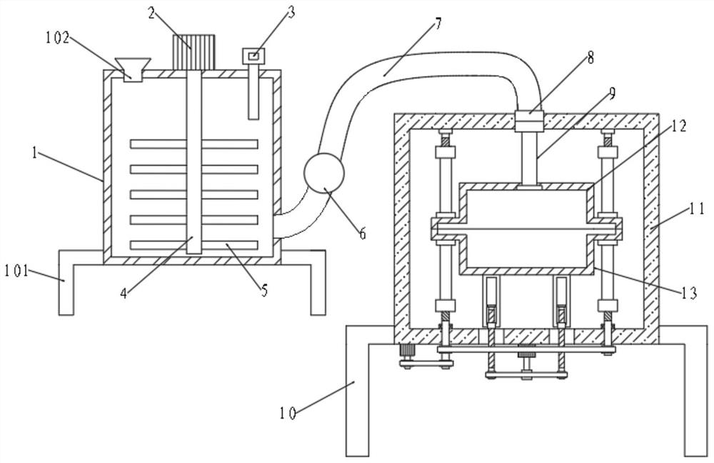
[0028] A rapid cooling and demoulding device for steel castings, comprising a working box 11, the bottom of the left and right ends of the working box 11 are symmetrically connected with outriggers 10, the front end of the working box 11 is correspondingly equipped with a box door, the middle part of the top of the working box 11 is connected with a joint 8, and the bottom There are through holes 111 symmetrically arranged on the left and right ends, and cooling components are installed on the working box 11;

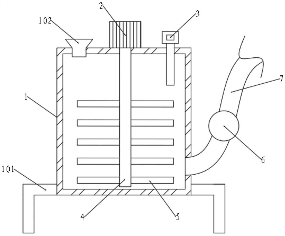
[0029] The upper end of the joint 8 is connected with a pouring pipe 7, the lower end of the joint 8 is connected with a feeding pipe 9, the pump 6 is installed on the pouring pipe 7, the other end of the pouring pipe 7 is connected with the stirring device, and the lower end of the feeding pipe 9 extends into and is fixedly connected with an upper Mold 12, and upper mold 12 cooperates with lower mold 13;

[0030] A solid mold structure is installed on the working box 1...

Embodiment 2

[0042] The difference from Example 1 is:

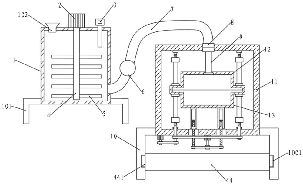
[0043] The opposite end of the support leg 10 is symmetrically provided with a chute 1001, and the chute 1001 is slidably connected with the slider 441, and the slider 441 is symmetrically arranged on the water receiving box 44, so as to facilitate the centralized collection of the water after the cooling treatment and avoid random discharge. polluted environment.

[0044] Working method: the steps are the same as those in Example 1, and will not be described in detail here. The difference is that a water receiving tank 44 is inserted on the leg 10, and the water receiving tank 44 can centrally collect the cooling waste liquid discharged from the through hole 111, which is convenient Subsequent treatment also solves the problem of random discharge of cooling waste liquid and protects the environment.

[0045] The motors, pumps, heaters and coolers used in this patent are all commercially available, and their structures and control me...


PUM


Abstract

The invention relates to the technical field of steel casting demolding, in particular to a rapid cooling and demolding device for a steel casting. According to the rapid cooling and demolding device for the steel casting, a mold for producing and forming the steel casting can be well fixed through a mold fixing structure, then added molten steel can be well mixed through a stirring device, uneven mass distribution during molten steel pouring is avoided, the molten steel is well poured between molds through the effect of a pump, meanwhile, a cooling device in a cooling assembly is matched with a water suction pump and a spray head, the spray head sprays cooling liquid to the surfaces of the molds, and rapid cooling treatment on the poured molds is achieved; before demolding, the mold fixing structure is controlled to be separated from the molds, then a third motor is driven to drive a demolding assembly to pull a lower mold downwards, the lower mold is separated from the formed steel casting, and a worker opens a box door to take out the produced formed steel casting; and a water collecting tank is arranged at the bottom of a working box of the device, cooling water is specially recycled, cooling waste liquid is prevented from being discharged at will, and the environment is protected.

Description

technical field [0001] The invention relates to the technical field of demoulding of steel castings, in particular to a rapid cooling and demoulding device for steel castings. Background technique [0002] Demoulding refers to a series of operations to release the steel ingot from the steel ingot mold. The time from the completion of pouring of steel ingots to demoulding, and the time from the completion of pouring of the last ingot of a barrel of steel to the start of demoulding of the first ingot is called the transfer time of steel ingots. Killed steel ingots require that the ingot body is completely solidified before the insulation cap can be removed. Semi-killed steel ingots and ebullient steel ingots can be demolded when the solidified layer reaches a certain thickness. [0003] The transfer time of various steel ingots in the mold depends on the solidification speed or complete solidification time of the steel ingots, which can be determined by empirical calculation ...

Claims


Application Information

Patent Timeline
IPC IPC(8): B22D33/06B22D1/00B22D35/04B22D27/04B22D29/08B22D7/06B22D7/12
CPCB22D33/06B22D1/00B22D35/04B22D27/04B22D29/08B22D7/064B22D7/12
Inventor 张伍胜王新剑
Owner 含山县大颉机械有限公司
Why Eureka
Try Eureka