
Automatic needle mounting mechanism

A needle-loading and automatic technology, applied in the direction of mechanical equipment, metal processing, bearing components, etc., to achieve the effect of improving stability, continuous mechanism, and high stability

Pending Publication Date: 2021-09-07
WANXIANGQIANCHAO CO LTD +1
View PDF1 Cites 0 Cited by
  • Summary
  • Abstract
  • Description
  • Claims
  • Application Information

AI Technical Summary

Problems solved by technology

[0004] The purpose of the present invention is to overcome the deficiencies in the above-mentioned background technology, provide an automatic needle loading mechanism, which can reduce vibration noise, avoid the situation of missing row and needle roller loading, realize full automation, save manual assembly operations, and improve the accuracy of assembly. needle efficiency

Method used


Image

  • Automatic needle mounting mechanism
  • Automatic needle mounting mechanism
  • Automatic needle mounting mechanism

Examples


Embodiment Construction

[0032] To enable one of ordinary skill in the art to more clearly understand the objectives, technical solutions, and advantages of the present invention, the following embodiments in conjunction with the accompanying drawings and further elaboration of the present invention, but the present invention is not limited to the following embodiments.

[0033] In the description of the present invention, it should be noted that, unless otherwise expressly specified or limited, to those of ordinary skill in the art, be appreciated that the specific circumstances of the specific meanings in general terms the present invention.

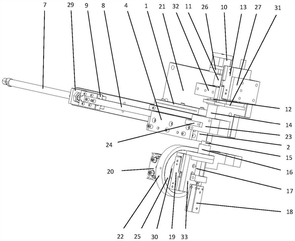
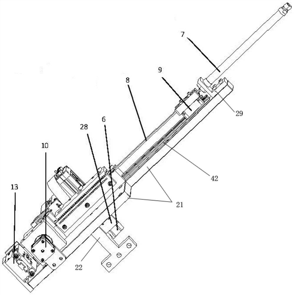
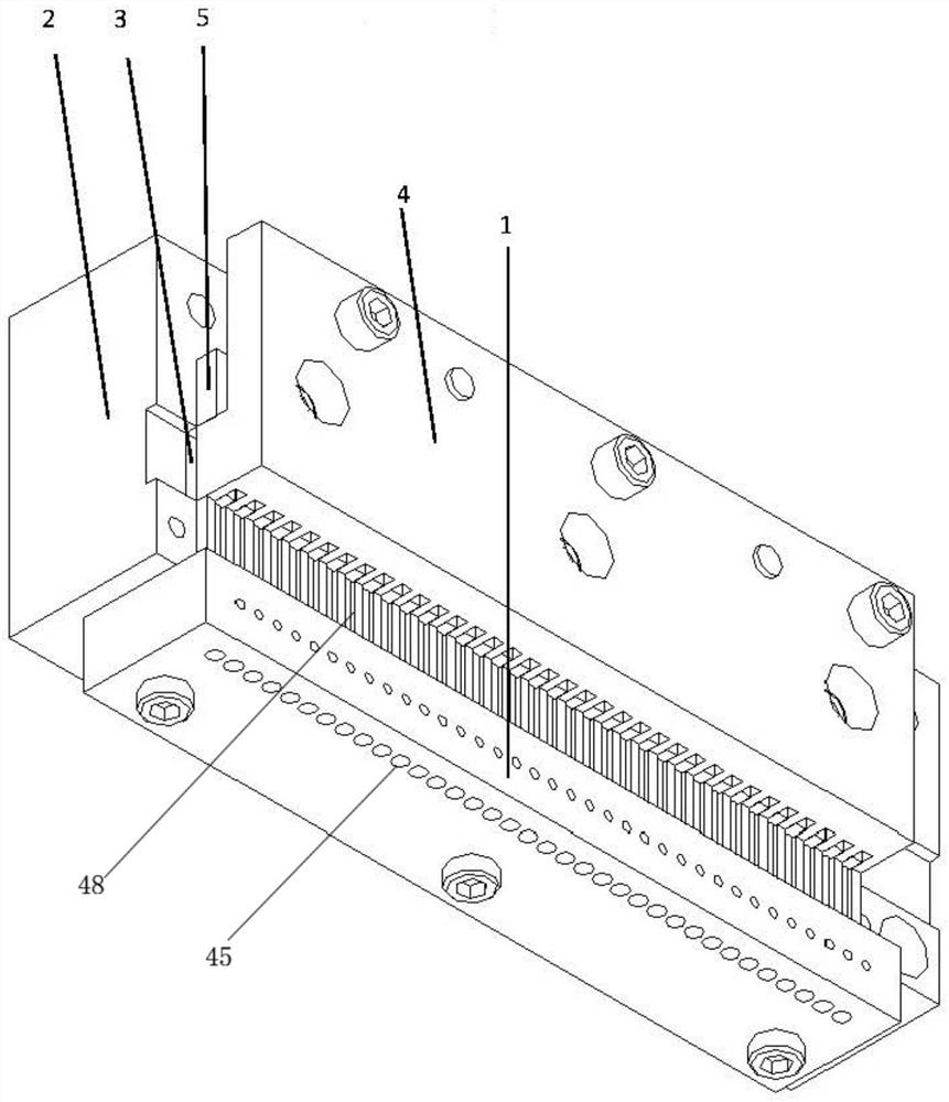
[0034] like figure 1 , figure 2 Shown, an automatic loading mechanism of the present invention provides a needle, comprising a needle assembly mounted on the frame by a mounting base plate 21, push the needle assembly, the needle assembly and a pin assembly. The needle assembly is provided with a pinhole 45 and a set of primers needle storage groove 49, the outer ...


PUM


Abstract

The invention relates to the technical field of automatic equipment, in particular to an automatic needle mounting mechanism. The automatic needle mounting mechanism comprises a needle feeding assembly, a needle pushing assembly, a needle arranging assembly and a needle discharging assembly. The needle feeding assembly is provided with a set of needle guiding holes and a needle storage groove, and the needle guiding holes guide rolling needles conveyed by an external rolling needle conveying mechanism into the needle storage groove. After a push rod of the needle pushing assembly is driven, the rolling needles in the needle storage groove are pushed into the needle arranging assembly. The needle arranging assembly is provided with a hollow block, a main shaft inserted into a needle arranging hole of the hollow block and a first push sleeve driven to stretch out and draw back, the rolling needles are pushed by the push rod to enter an annular cavity between the main shaft and the hole wall of the needle arranging hole to be arranged into a circle, and the circled rolling needles are pushed into the needle discharging assembly through the first push sleeve. The needle discharging assembly is provided with a sleeve driven to stretch out and draw back, a center shaft which stretches into the sleeve and stretches out and draw back together with the sleeve and a second push sleeve driven to stretch out and draw back, and the circled rolling needles are pushed by the first push sleeve to enter an annular cavity between the center shaft and the sleeve and then are pushed into a bearing workpiece through the second push sleeve.

Description

Technical field [0001] The present invention relates to the field of automation technology device, in particular an automatic needle loading mechanism. Background technique [0002] Currently bearing or universal joint cross shaft needle hub assembly, they use autoloader machine needle assembly, such as Chinese invention an automatic apparatus disclosed in CN01210727.1 needle machine, by a motor via a transmission line and means provided on the needle funnel cover, the drive spindle mounted within the needle funnel means is provided below the dial needle funnel, which is provided with a fixed outer sleeve and the outer sleeve equipped with a mandrel placed in the mold sleeve, between its upper opening and the needle with the mandrel forms a ring groove arrangement adapted. [0003] Autoloader disadvantages of the prior needle machine are: 1, the use of a motor, a belt drive rocker mechanism, the crank and rocker mechanism rocker fast swing back and forth, using the vibration char...

Claims


Application Information

Patent Timeline
IPC IPC(8): B23P19/04F16C43/06
CPCB23P19/04B23P19/001F16C43/06
Inventor 王德进史伟国张银桥付梅军刘渭黄李琳张浩杰严国平
Owner WANXIANGQIANCHAO CO LTD
Learn More