Check patentability & draft patents in minutes with Patsnap Eureka AI!

New energy automobile power conversion system and matched computer conversion control method

A technology for power conversion systems and new energy vehicles, which is applied to the layout of multiple different prime movers of general power plants, the conversion of light energy to electric energy, and the conversion of air flow to electric energy, etc., which can solve complex structures and poor fuel-saving effects. Obvious problems, to achieve the effect of improving battery life, improving power performance and driving experience, and realizing multi-effect power generation

Active Publication Date: 2021-09-07
SHANDONG POLYTECHNIC COLLEGE +1
View PDF6 Cites 0 Cited by
  • Summary
  • Abstract
  • Description
  • Claims
  • Application Information

AI Technical Summary

Problems solved by technology

However, the existing hybrid energy vehicles usually have a very complex structure and the fuel-saving effect is not obvious in the state of long-distance high-speed driving

Method used


Image

  • New energy automobile power conversion system and matched computer conversion control method
  • New energy automobile power conversion system and matched computer conversion control method

Examples


Embodiment 1

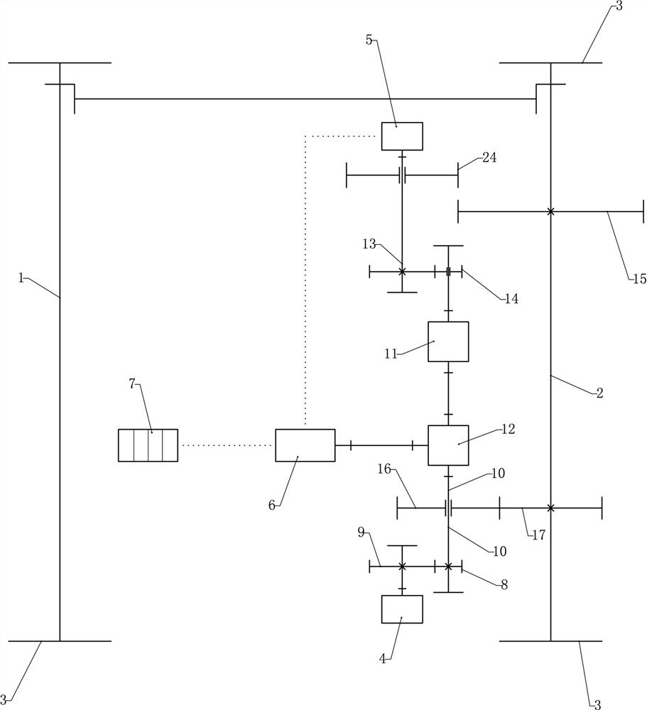
[0035] The new energy vehicle power conversion system includes a fuel power device, a power generation device, and an energy storage device. Both the fuel power device and the power generation device are connected to the vehicle running mechanism through a power separation device. The power generating devices are connected or separated by an automatic clutch device, and the power generating devices are used to provide power for the traveling mechanism of the vehicle and provide electric energy for the energy storage device.

[0036] As the main drive structure, the fuel power unit and the power generation unit can realize the mixed use of gasoline and electricity, and control the operation sequence to realize pure electric drive or oil drive or hybrid electric drive. Multiple driving modes can effectively increase the power demand of the car and battery life requirements.

[0037] In any of the above schemes, preferably, the vehicle running mechanism comprises a vehicle front ...

Embodiment 2

[0047] Compared with embodiment 1, the improvements are:

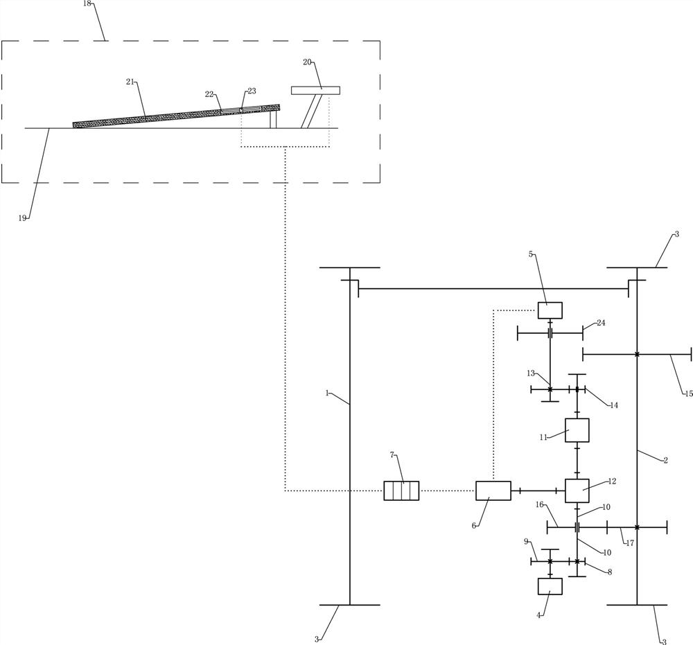
[0048] In any of the above schemes, preferably, the new energy vehicle power conversion system further includes a multi-effect solar power generation device 18 .

[0049] The storage battery pack 7 is connected with the multi-effect solar power generation device 18 through wires.

[0050] At the same time, the multi-effect solar power generation device 18 provided with the power generation of the engine 4 can effectively improve the power generation capacity of the entire system, and further improve the continuous battery life.

[0051] Preferably in any of the above schemes, the multi-effect solar power generation device 18 includes a solar photovoltaic panel flank 20 fixedly installed on the rear end of the vehicle roof 19, a solar main photovoltaic panel 21 fixedly installed in the middle section of the vehicle roof 19, and the solar energy The rear end of the main photovoltaic panel 21 is inclined upward, and a wi...


PUM


Abstract

The invention relates to the technical field of new energy automobiles, and in particular relates to a new energy automobile power conversion system and a matched computer conversion control method. The new energy automobile power conversion system comprises a fuel oil power device, a power generation device and an energy storage device, the fuel oil power device and the power generation device are both connected with an automobile walking mechanism through a power separation device, the fuel oil power device and the power generation device are connected or separated through an automatic clutch device, and the power generation device is used for providing power for the automobile walking mechanism and providing electric energy for the energy storage device. The system provides double hybrid power for the new energy automobile, the optimal power source can be selected and matched according to different working conditions during use, and the power performance and driving experience of the automobile can be effectively improved; oil drive serves as main power, meanwhile, oil drive matches electric drive to serve as starting power under large torque, and the climbing performance and other performance of the automobile can be effectively improved.

Description

technical field [0001] The invention relates to the technical field of new energy vehicles, in particular to a new energy vehicle power conversion system and a matching computer conversion control method. Background technique [0002] New energy vehicles mainly refer to the use of unconventional vehicle fuels as power sources or the use of conventional vehicle fuels, the use of new vehicle power devices, the integration of advanced technologies in vehicle power control and driving, and the formation of advanced technical principles and innovative features. Technology, new structure of the car. [0003] As one of the main types of hybrid energy vehicles in new energy vehicles, the structural form and control method of the hybrid drive system of hybrid energy vehicles aims to optimize the matching of the engine, generator, motor and other components. , so as to ensure that the system works in the optimal state under more complex working conditions. However, the existing hybr...

Claims


Application Information

Patent Timeline
IPC IPC(8): B60K6/22B60K6/26B60K6/38B60L8/00B60W20/00
CPCB60K6/22B60K6/26B60K6/38B60L8/003B60L8/006B60W20/00Y02T10/7072
Inventor 姚娜惠莹明玲屈道宽
Owner SHANDONG POLYTECHNIC COLLEGE
Features
  • R&D
  • Intellectual Property
  • Life Sciences
  • Materials
  • Tech Scout
  • Unparalleled Data Quality
  • Higher Quality Content
  • 60% Fewer Hallucinations
Learn More