Three-dimensional optical coherence elastography detection device applied to corneal refraction operation

A refractive surgery, three-dimensional optical technology, applied in the field of three-dimensional optical coherent elastography detection devices, can solve the problems of affecting the detection results, contamination of debris, contamination of convex lenses with debris, etc.

Active Publication Date: 2021-09-07
中山大学中山眼科中心南昌眼科医院
View PDF18 Cites 0 Cited by
  • Summary
  • Abstract
  • Description
  • Claims
  • Application Information

AI Technical Summary

Problems solved by technology

[0004] In order to overcome the shortcomings that manual loading and unloading of the convex lens will cause the convex lens to be contaminated with impurities, thereby affecting the detection results, and requiring a lot of time and energy, the purpose of the present invention is to provide a method that can prevent the convex lens from being contaminated with debris and Three-dimensional optical coherence elastography detection device with high work efficiency for corneal refractive surgery

Method used


Image

  • Three-dimensional optical coherence elastography detection device applied to corneal refraction operation
  • Three-dimensional optical coherence elastography detection device applied to corneal refraction operation
  • Three-dimensional optical coherence elastography detection device applied to corneal refraction operation

Examples


Embodiment 1

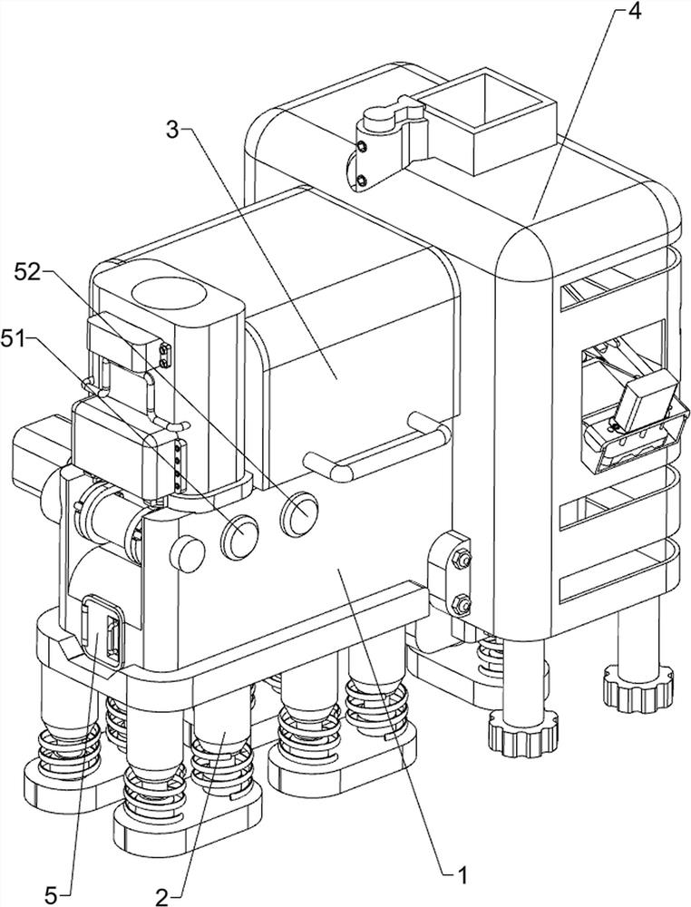
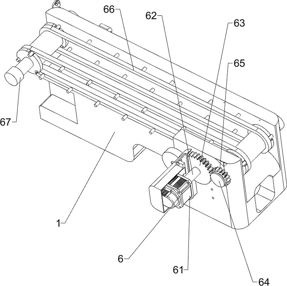
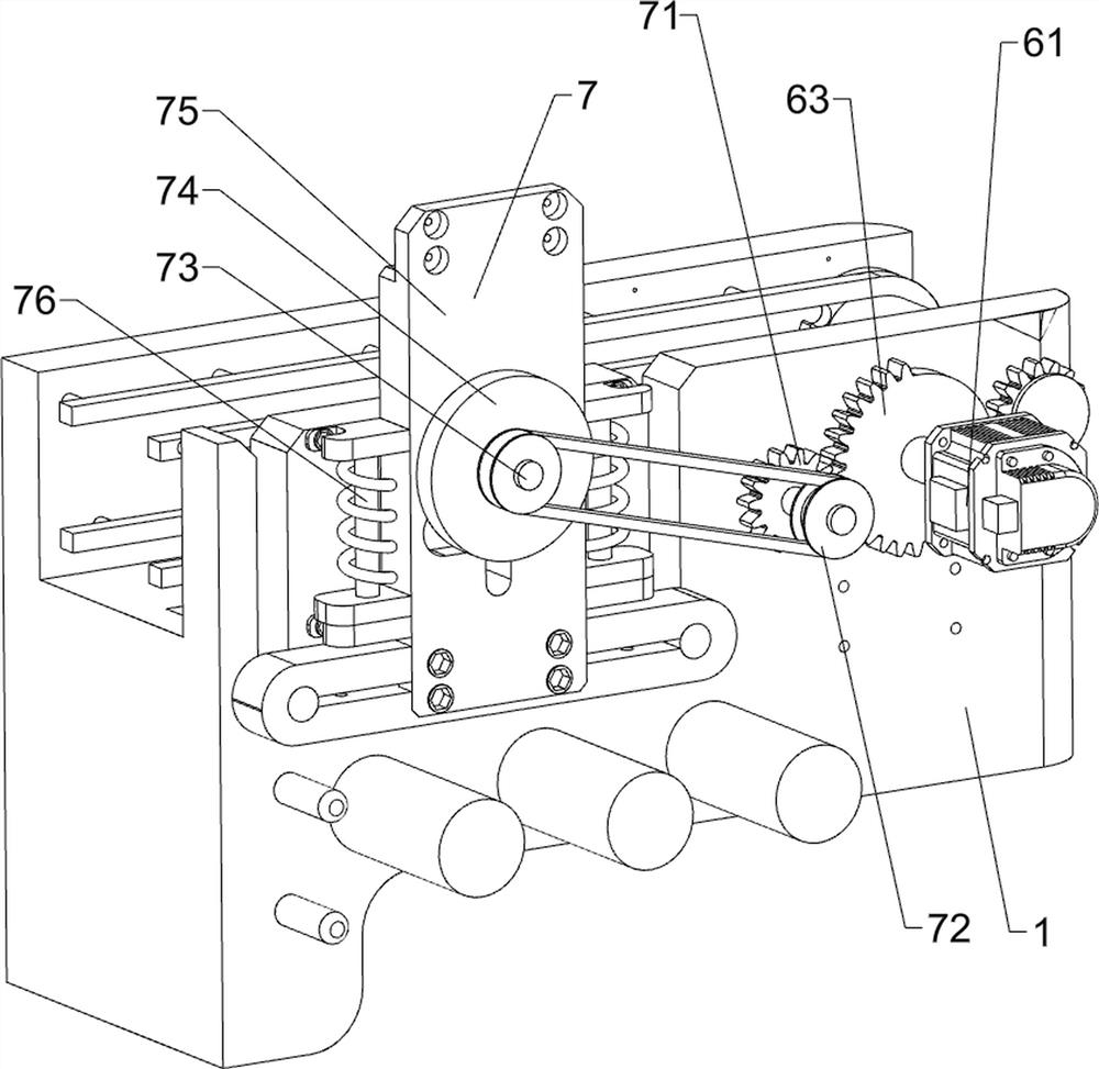
[0089] A three-dimensional optical coherence elastography detection device applied to corneal refractive surgery, such as Figure 1-Figure 6 As shown, it includes a detection box 1, a buffer base 2, a light-shielding cover 3, a protective cover 4, a start button 51, a stop button 52, a feeding mechanism 6 and a detection mechanism 7, and the bottom of the detection box 1 is provided with a plurality of Buffer base 2, a light-shielding cover 3 is provided on the left side of the top of the detection box body 1, a protective cover 4 is provided on the right side of the detection box body 1, a start button 51 is provided on the front left side of the upper part of the detection box body 1, and a start button 51 is provided on the upper front side of the detection box body 1. The left side is provided with a stop button 52, and the stop button 52 is positioned at the right side of the start button 51. The top of the detection box 1 is provided with a feeding mechanism 6, and the ri...

Embodiment 2

[0094] On the basis of Example 1, such as Figure 7-Figure 15 As shown, also includes feeding mechanism 8, and feeding mechanism 8 includes charging cylinder 81, safety baffle plate 82, lifting inclined block frame 83, return spring post 84, positioning top plate 85, material retaining tongue plate 86, water tank 87 , an atomizing device 88, an air duct 89 and a first pressure sensor 810, a charging tube 81 is arranged on the left side of the top of the detection box 1, and the charging tube 81 is located on the left side of the light-shielding cover 3, and the lower part of the left side of the charging tube 81 is provided There is a safety baffle 82, and the bottom left side of the charging cylinder 81 is provided with a positioning top plate 85, and the positioning top plate 85 is positioned at the inner side of the safety baffle 82, and four return spring columns 84 are arranged at intervals on the left side of the bottom of the positioning top plate 85, and the bottom of t...


PUM


Abstract

The invention relates to a detection device, in particular to a three-dimensional optical coherence elastography detection device applied to a corneal refractive operation. The invention aims to provide the three-dimensional optical coherence elastography detection device applied to the corneal refraction operation, the device can prevent a convex lens from being contaminated by impurities and is relatively high in working efficiency. The three-dimensional optical coherence elastography detection device applied to the corneal refraction operation comprises a detection box body, buffer bases, a shading cover plate, a protection cover and a start button. The multiple buffer bases are arranged at the bottom of the detection box body at intervals, the shading cover plate is arranged on one side of the top of the detection box body, the protection cover is arranged on one side of the detection box body, and the start button is arranged on one side of the upper portion of the detection box body. According to the three-dimensional optical coherence elastography detection device applied to the corneal refraction operation, through cooperation of a material conveying mechanism and a detection mechanism, a convex lens can be automatically conveyed and subjected to light transmittance detection, people do not need to hold the convex lens with hands, and light transmittance detection is prevented from being affected.

Description

technical field [0001] The invention relates to a detection device, in particular to a three-dimensional optical coherent elastic imaging detection device applied to corneal refractive surgery. Background technique [0002] Optical coherent elastography is a technology that takes elastic parameters such as Young's modulus, shear modulus, stress and strain of soft tissue as the imaging object. Along with the development of optical coherence tomography (OCT), optical coherence elastography (OCE) has been favored by people due to its micron-level resolution, real-time image processing and non-invasive imaging. For corneal refractive surgery, real-time image processing and analysis are required, so the use of optical coherence elastography is inevitable. [0003] At present, in corneal refractive surgery, the convex lens is a common optical element. In order to better observe the image, it is necessary to test the light transmission of the convex lens. When people test the ligh...

Claims


Application Information

Patent Timeline
Patent Type & Authority Applications(China)
IPC IPC(8): B65B57/10B65B63/00G01M11/02
CPCB65B57/10B65B63/00G01M11/02G01M11/0292G01M11/0207
Inventor 黄国富赵雁之
Owner 中山大学中山眼科中心南昌眼科医院
Why Eureka
Try Eureka