Vehicle-mounted storage bin for cargo transportation
A technology for cargo transportation and storage bins, which is applied to the field of storage bins for cargo transport vehicles, can solve the problems of increasing labor intensity, trouble, and trouble, and achieve the effects of reducing labor intensity, improving safety, and improving work efficiency.
- Summary
- Abstract
- Description
- Claims
- Application Information
AI Technical Summary
Problems solved by technology
Method used
Image

Examples
Embodiment 1
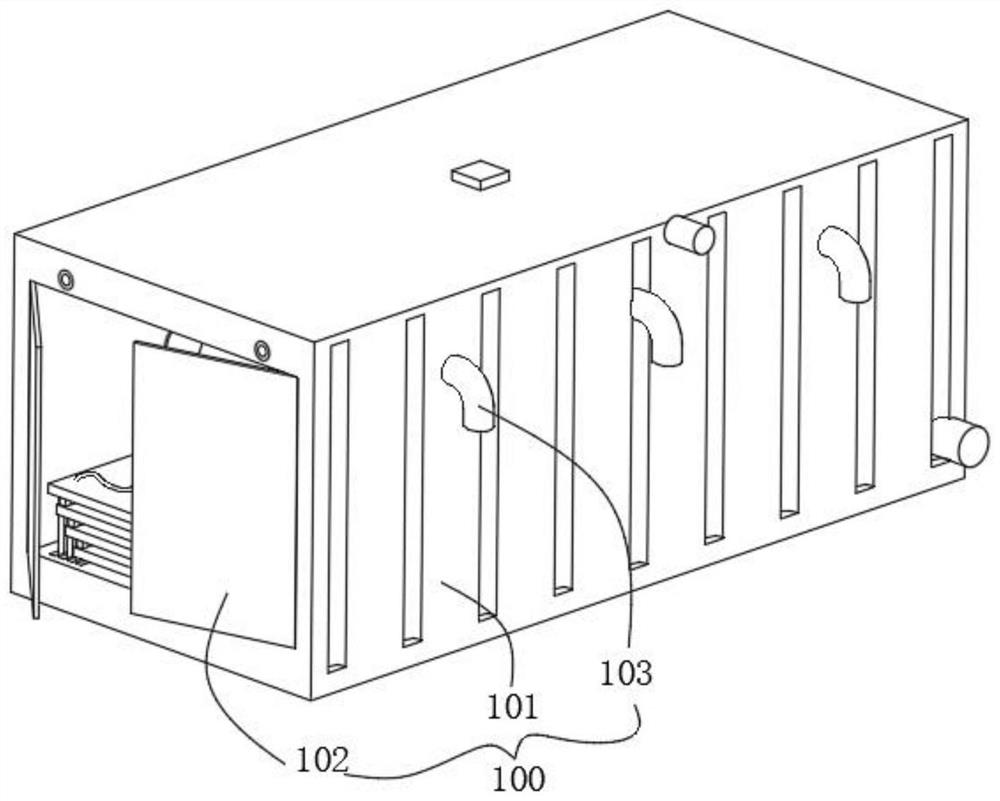
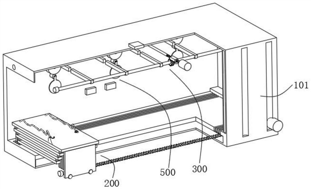
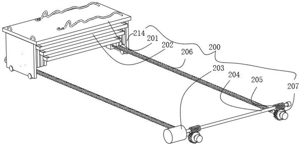
[0049] combine figure 1 , 2 , 3 and 4, the vehicle-mounted storage bin for cargo transport provided by the present invention includes a bin body 100, a transmission mechanism 200, a blocking mechanism 300, a pushing mechanism 400, and a ventilation mechanism 500, and the bin body 100 includes a housing 101 and is arranged on The protective door 102 on the housing 101, the inner bottom of the housing 101 is provided with an equipment cavity, the transmission mechanism 200 includes a first motor 203 fixed in the equipment cavity, a transmission shaft 204 fixed at the output end of the first motor 203, The worm 205 set on both sides of the transmission shaft 204, the screw 206 rotatably installed on both sides of the equipment cavity, the worm wheel 207 set on the screw 206 and meshed with the worm 205 for transmission, and the first transmission plate suitable for sliding relative to the screw 206 214 and the first support platform 201 fixed on the first transmission plate 214,...
Embodiment 2
[0054] combine figure 2 and 6 As shown, on the basis of the first embodiment, the barrier mechanism 300 includes a connecting shaft 304 rotatably installed on both sides of the upper side of the housing 101, a plurality of baffles 306 sleeved on the connecting shaft 304, and fixed on the housing 101. The second motor 301, the two-way screw rod 302 fixedly connected to the output end of the second motor 301, the gear plate 303 suitable for sliding on both sides of the two-way screw rod 302, the gear plate 303 that is sleeved on the connecting shaft 304 and meshed with the gear plate 303 for transmission Gear 305, the end face of the tooth plate 303 fits with the inner upper wall of the housing 101, a plurality of the baffle plates 306 are equidistantly distributed, and the second motor 301 starts to drive the two-way screw rod 302 to rotate, so that the tooth plates on both sides 303 moves in the opposite direction, the gear plate 303 and the gear 305 are meshed for transmiss...
Embodiment 3
[0057] combine Figure 4 and 5 As shown, in the above embodiment, the pushing mechanism 400 includes a first motor 401 fixed to the inner side walls of the first support platform 201 and the second support platform 202, a rotating shaft 402 fixed to the output end of the first motor 401 and a sleeve The push blocks 403 on both sides of the rotating shaft 402, the bottoms of the first supporting platform 201 and the second supporting platform 202 are provided with transmission grooves corresponding to the pushing blocks 403, the first motor 401 starts to drive the rotating shaft 402 to rotate, and the pushing blocks 403 rotates with the rotating shaft 402, and the pushing block 403 is rotated to the bottom, and then when the first supporting platform 201 and the second supporting platform 202 are reset, the first supporting platform 201 pushes the second supporting platform 202 through the transmission block 209 To move, the second support platform 202 pushes the second suppor...
PUM
 Abstract
Description
Claims
Application Information
 - R&D Engineer
- R&D Manager
- IP Professional
- Industry Leading Data Capabilities
- Powerful AI technology
- Patent DNA Extraction
Browse by: Latest US Patents, China's latest patents, Technical Efficacy Thesaurus, Application Domain, Technology Topic.
© 2024 PatSnap. All rights reserved.Legal|Privacy policy|Modern Slavery Act Transparency Statement|Sitemap