Eureka AIR delivers breakthrough ideas for toughest innovation challenges, trusted by R&D personnel around the world.

Rectangular concrete column-H-shaped beam composite ring plate type connecting joint and connecting method

A technology for concrete columns and connecting nodes, which can be used in buildings, building structures, etc., and can solve the problems of small size, large welding workload, and high welding process requirements.

Pending Publication Date: 2021-09-07
CHINA NORTHWEST ARCHITECTURE DESIGN & RES INST CO LTD
View PDF0 Cites 0 Cited by
  • Summary
  • Abstract
  • Description
  • Claims
  • Application Information

AI Technical Summary

Problems solved by technology

However, due to the small cross-sectional size of rectangular steel tube concrete columns, the connection forms of common joints such as square steel tube column-H-shaped steel beam joints and circular steel tube column-H-shaped steel beam joints cannot be applied to this type of joints.
For example: the inner diaphragm type connection and the diaphragm penetrating type connection will hinder the concrete pouring inside the rectangular steel pipe column; the outer ring plate type joint size is large, which brings inconvenience to the construction space; It is damaged and the construction site requires overhead welding and side welding. The welding process requires high requirements, large welding volume, and slow construction speed; the bolted connection will cause unevenness of the column wall, which will affect the pouring and vibration of the concrete; the high strength of the window opening on the column wall The bolted connection will weaken the integrity of the steel pipe column, and the welding workload is heavy, and the welding quality is not easy to guarantee

Method used


Image

  • Rectangular concrete column-H-shaped beam composite ring plate type connecting joint and connecting method
  • Rectangular concrete column-H-shaped beam composite ring plate type connecting joint and connecting method

Examples


Embodiment 1

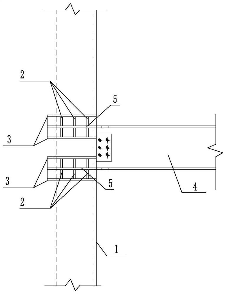
[0047] see figure 1 and figure 2 , the rectangular concrete column-H-shaped beam composite ring plate connection node in this embodiment, which includes a ring plate 3, at the junction of the upper flange plate of the H-shaped steel beam 4 and the rectangular concrete-filled steel tube column 1 and at the junction of the H-shaped steel beam 4 The connection between the lower flange plate and the rectangular concrete-filled steel tube column 1 is provided with an annular connecting plate 5, which is sleeved on the rectangular concrete-filled steel tube column 1 and welded to the rectangular concrete-filled steel tube column 1. A ring plate 3 is provided above the annular connecting plate 5 and below the annular connecting plate 5 of the upper flange plate, and a ring plate 3 is provided above the annular connecting plate 5 of the lower flange plate and below the annular connecting plate 5 of the lower flange plate , the ring plate 3 is sleeved around the rectangular steel tub...

Embodiment 2

[0049] The difference from Example 1 is that in this example, the rectangular concrete column-H-shaped beam composite ring plate connection node, its t 1 The value of is 21㎜, the width of the H-shaped steel beam 4 is 300㎜, b 1 =0.7*300㎜=210㎜, t 2 = t 3 = 25㎜, b 2 =b 3 =60㎜, then (b 1 *t 1 ) / (b2 *t 2 ) = (b 1 *t 1 ) / (b 3 *t 3 )=(210*21) / (60*25)=2.94, rounded m=n=3, that is, the number of ring plates 3 at the corresponding position of the upper flange plate is 6, and the ring plate at the corresponding position of the lower flange plate The number of 3 is 6, then the thickness t of the upper flange plate 4 ≥23㎜, the thickness of the lower flange plate t 5 ≥23㎜; the distance between two adjacent ring plates 3 above the annular connecting plate 5 of the upper flange plate and below the annular connecting plate 5 of the upper flange plate is 50 mm, and at the annular connecting plate 5 of the lower flange plate The distance between two adjacent ring plates 3 below the ...

Embodiment 3

[0051] The difference from Example 1 is that in this example, the rectangular concrete column-H-beam composite ring plate connection node has 10 ring plates 3 at the corresponding position of the upper flange plate, and 10 ring plates 3 at the corresponding position of the lower flange plate. The number of 3 is 10, and the distance between two adjacent ring plates 3 above the annular connecting plate 5 of the upper flange plate and below the annular connecting plate 5 of the upper flange plate is 80mm, and at the annular connecting plate 5 of the lower flange plate The distance between two adjacent ring plates 3 above the connecting plate 5 and below the annular connecting plate 5 of the upper flange plate is 80mm; the rest are the same as in the first embodiment.


PUM


Abstract

The invention provides a rectangular concrete column-H-shaped beam composite ring plate type connecting joint and a connecting method, and belongs to the technical field of building construction design. the rectangular concrete column-H-shaped beam composite ring plate type connecting joint comprises a ring plate, the ring plate is arranged corresponding to an upper flange plate and a lower flange plate of an H-shaped steel beam, and the ring plate surrounds a rectangular steel pipe concrete column; annular connecting plates are arranged on the upper flange plate and the lower flange plate of the H-shaped steel beam and surround the rectangular concrete filled steel tubular column, and the annular connecting plates and the annular plates are arranged in parallel. According to the composite ring plate type connecting joint, it can be guaranteed that force transmission process between the rectangular steel pipe concrete column and the H-shaped steel beam is reliable, and construction can be facilitated.

Description

technical field [0001] The invention belongs to the technical field of building construction design, and relates to the design technology of the connection structure between a steel pipe concrete column and a steel beam, in particular to a rectangular concrete column-H-shaped beam composite ring plate connection node and a connection method. Background technique [0002] In the past 10 years, my country has built super high-rise buildings with a height of 200m to 400m, most of which adopt steel frame-core tube structure. The outer frame adopts steel reinforced concrete or steel pipe concrete columns, and the floor beam adopts H-shaped steel beams, which can improve the performance difference between the steel frame and the concrete core tube due to creep and shrinkage, and form a hybrid frame-reinforced concrete core tube (Hybrid) structure, the hybrid frame is suitable for rectangular steel tube concrete frame columns. With the development of the prefabricated steel struct...

Claims


Application Information

Patent Timeline
Patent Type & Authority Applications(China)
IPC IPC(8): E04B1/18E04B1/58
CPCE04B1/185
Inventor 辛力史生志李冰
Owner CHINA NORTHWEST ARCHITECTURE DESIGN & RES INST CO LTD
Why Eureka
Eureka Blog
Learn More