Disc dryer convenient in tail gas treatment

A technology for disc dryers and dryers, applied in non-progressive dryers, dryers, drying solid materials, etc., which can solve problems such as large tail gas volume, excessive air particle size, and air pollution

Pending Publication Date: 2021-09-07
CHANGZHOU MINGLIU DRYING EQUIP
View PDF0 Cites 0 Cited by
  • Summary
  • Abstract
  • Description
  • Claims
  • Application Information

AI Technical Summary

Problems solved by technology

[0004] The object of the present invention is to provide a disc dryer which is convenient for tail gas treatment, which solves the problem of the disc dryer in the prior art. Dust particles, ca...

Method used


Image

  • Disc dryer convenient in tail gas treatment
  • Disc dryer convenient in tail gas treatment
  • Disc dryer convenient in tail gas treatment

Examples


Embodiment 1

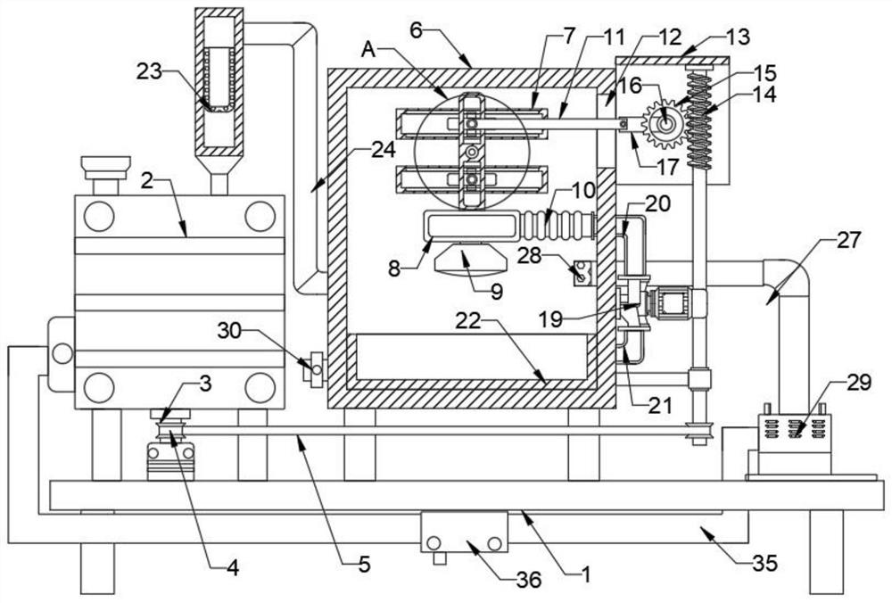
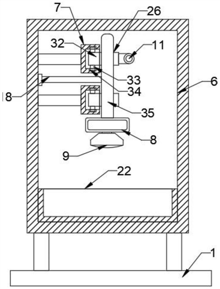
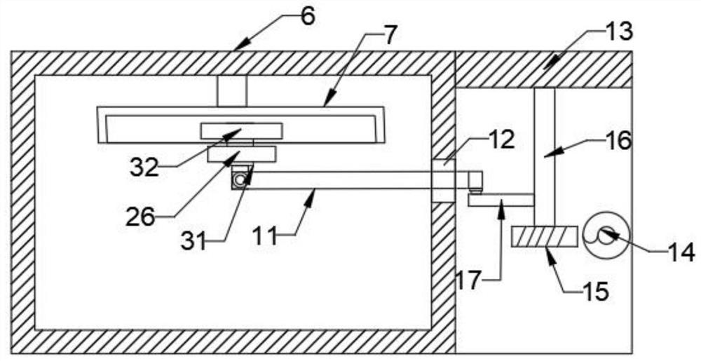
[0027] refer to Figure 1-4 , including a base 1, characterized in that the top side of the base 1 is fixedly connected with a dryer body 2, the dryer body 2 includes a main shaft 3, the top side of the base 1 is fixedly connected with a box body 6, and the upper part of the box body 6 is along the Two bearing frames 7 are fixedly connected in the vertical direction, and the inner sides of the two bearing frames 7 are slidingly connected with movable blocks 32, and the two movable blocks 32 are fixedly connected with projections 31, one of the two bearing frames 7 The side is provided with a moving rod 26 that is rotatably connected to the inner wall of the box body 6, and the upper and lower parts of the moving rod 26 are provided with movable grooves 25 for use with the protrusions 31, and one of the two protrusions 31 is rotated by a pin shaft. A movable rod 11 that runs through the side wall of the box body 6 is connected, a fixed frame 13 is fixedly connected to one side ...

Embodiment 2

[0030] refer to Figure 1-4 , the moving rod 26 is fixedly connected with a support rod 18 near the inner wall side of the box body 6, and one end of the support rod 18 is rotationally connected with the inner wall of the box body 6 through a rotating shaft, and the top and bottom of the two movable blocks 32 are fixedly connected There is a sliding block 33, and the sliding block 33 is slidably connected with the inner wall of the bearing frame 7 through the chute 34, and the sliding block 33 is used to slide in the chute 34, thereby further enhancing the stability of the movable block 32.

Embodiment 3

[0032] refer to Figure 1-4 , the air inlet of the blower fan 29 is connected with an air outlet pipe 27, and the air inlet of the air outlet pipe 27 is connected with the middle part of the box body 6, and the air outlet of the fan 29 is connected with a return pipe 35, and the return pipe 35 The extended end of the dryer body 2 communicates with each other, and a low-temperature water removal device 36 is installed on the return pipe 35. The high-humidity gas is processed in the low-temperature water removal device 36 to remove water vapor, and enters the dryer again through the return pipe 35 In the heater on the body 2, a closed cycle is achieved to avoid emissions.


PUM


Abstract

The invention relates to the technical field of drying machines, in particular to a disc type drying machine convenient in tail gas treatment and aims at solving the problems that in the drying process, the quantity of flowing air is large, the quantity of exhausted tail gas is large, and the exhausted tail gas contains fine dust particles, so that the air granularity exceeds the standard; and particularly, air pollution is caused by solvents discharged into the atmosphere when materials containing irritant organic solvents are dried of a disc type drying machine in the prior art are solved. The disc type drying machine convenient in tail gas treatment comprises a base, wherein a drying machine body is fixedly connected to one side of the top of the base and comprises a main shaft, a box body is fixedly connected to one side of the top of the base, and two bearing frames are fixedly connected to the upper part of the box body in a vertical direction. For the disc type drying machine convenient in tail gas treatment, with the mode provided by the invention, fine dust in tail gas is subjected to high-mesh filtration through a bag-type dust collector and then is sprayed through cooling water in the box body, so that the purpose of dual dust removal is achieved, and the dust removal efficiency is greatly improved.

Description

technical field [0001] The invention relates to the technical field of dryers, in particular to a disc dryer which is convenient for tail gas treatment. Background technique [0002] In the middle of the last century, during the industrialization of the disc drying technology, contact drying equipment was developed for the drying process requirements. In daily life and production, it is often necessary to dry various materials. The disc dryer is intermittent On the basis of the stirring conduction dryer, a series of advanced technologies have been integrated and developed through continuous improvement. It is a multi-layer fixed hollow heating circular loading tray, rotary rake stirring, vertical continuous drying equipment mainly based on heat conduction. , The disc dryer will produce a certain amount of tail gas during the drying process, which needs to be treated. [0003] The disc dryer in the prior art has a large flow air volume during the drying process, and a large ...

Claims


Application Information

Patent Timeline
IPC IPC(8): F26B11/18B01D46/02B01D47/06F26B25/00
CPCF26B11/184B01D46/023B01D47/06F26B25/007
Inventor 高定桃
Owner CHANGZHOU MINGLIU DRYING EQUIP
Why Eureka
Try Eureka