Disassembling device for waste battery recycling
A waste battery, sliding connection technology, applied in the direction of battery recycling, recycling technology, waste collector recycling, etc., can solve the problem of unsafe and destructive disassembly
- Summary
- Abstract
- Description
- Claims
- Application Information
AI Technical Summary
Problems solved by technology
Method used
Image
Examples
Embodiment 1
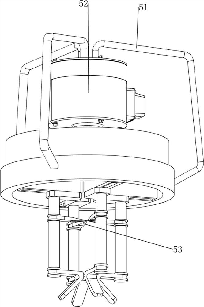
[0069] A dismantling device for recycling waste batteries, such as figure 1 As shown, it includes a bottom plate 1, a support frame 2, a connecting chassis 3, a feeding mechanism 4, a rotary cutting mechanism 5, and a feeding mechanism 6. Three support frames 2 are uniformly arranged on the bottom plate 1, and the tops of the three support frames 2 A connection chassis 3 is connected, and a discharge mechanism 4 is provided on the connection chassis 3. A rotary cutting mechanism 5 is provided on the discharge mechanism 4. A feeding mechanism 6 is provided between the connection chassis 3 and the bottom plate 1.
[0070] When people need to disassemble waste batteries, they can use this dismantling device for recycling waste batteries. First, people put the waste batteries on the feeding mechanism 6, then start the feeding mechanism 6, and the feeding mechanism 6 moves upward to drive The battery moves upwards. When the battery is moved to the discharge mechanism 4, people star...
Embodiment 2
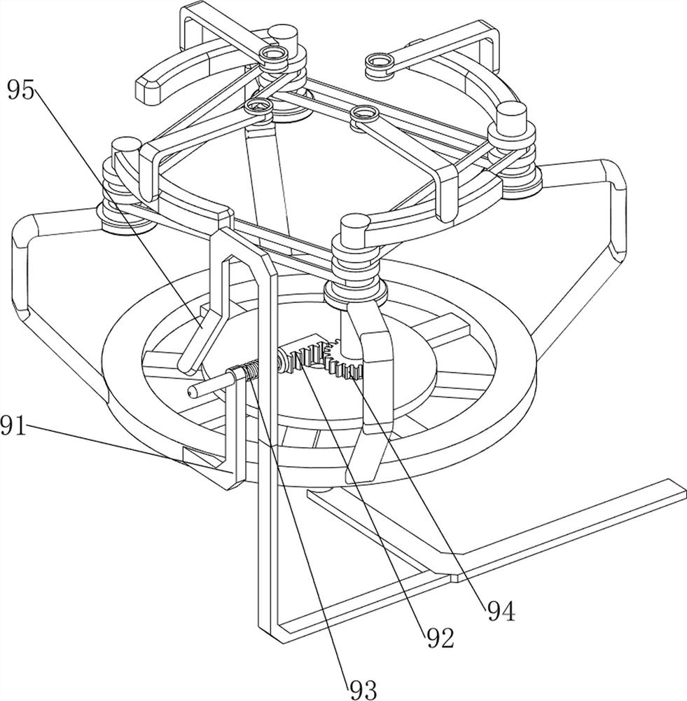
[0072] On the basis of Example 1, such as Figure 2-6 As shown, the discharge mechanism 4 includes a rotating support rod 41, a rotating connecting ring 42, a sliding connecting frame 43, a first sliding connecting rod 44, a first spring 45 and a sliding placement plate 46, and the connecting chassis 3 is provided with a rotating supporting rod 41, the rotating support rod 41 is provided with a rotating connecting ring 42, and the lower part of the rotating connecting ring 42 is evenly provided with four sliding connecting frames 43, and the sliding connecting frame 43 is provided with a first sliding connecting rod 44, the first sliding A first spring 45 is connected between the connecting rod 44 and the sliding connecting frame 43 , and the lower part of the first sliding connecting rod 44 is provided with a sliding placement plate 46 .
[0073] People put the battery on the feeding mechanism 6, then start the feeding mechanism 6, the upward movement of the feeding mechanism...
Embodiment 3
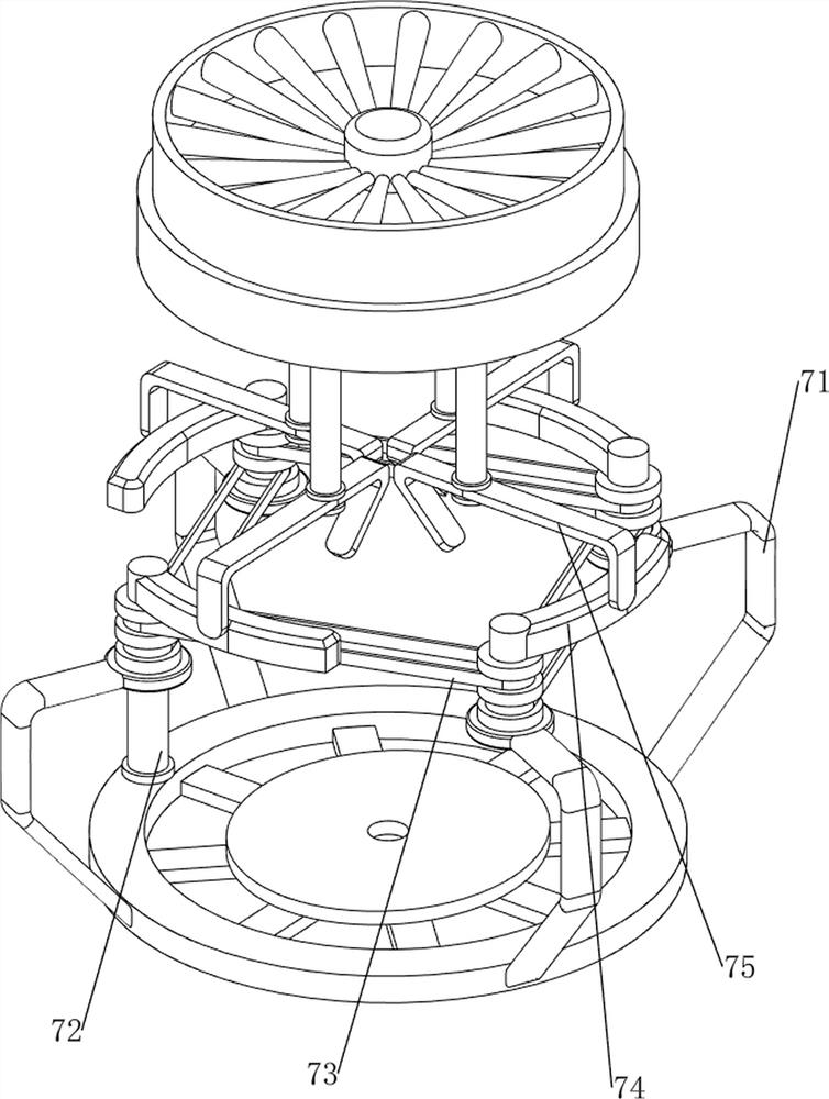
[0079] On the basis of Example 2, such as Figure 7-9 As shown, it also includes a cutting mechanism 7. The cutting mechanism 7 includes a rotating fixed rod 71, a rotating shaft 72, a transmission assembly 73, a rotating driving rod 74 and a driving connecting rod 75. The connecting chassis 3 is evenly equipped with four rotating fixed rods. Rod 71, rotation type is provided with rotating shaft 72 on the rotating fixed rod 71, and transmission assembly 73 is wound around between two adjacent rotating shafts 72, and transmission assembly 73 has four, and rotating shaft 72 is provided with rotation driving rod 74, slides and places plate 46 outsides are provided with driving connecting rod 75, and driving connecting rod 75 cooperates with rotating driving rod 74.
[0080] When the battery is disassembled, people manually turn the right rotating shaft 72, so that the transmission components 73 on the front and rear sides rotate, and then the four rotating shafts 72 and the four ...
PUM
 Abstract
Description
Claims
Application Information
 - R&D
- Intellectual Property
- Life Sciences
- Materials
- Tech Scout
- Unparalleled Data Quality
- Higher Quality Content
- 60% Fewer Hallucinations
Browse by: Latest US Patents, China's latest patents, Technical Efficacy Thesaurus, Application Domain, Technology Topic, Popular Technical Reports.
© 2025 PatSnap. All rights reserved.Legal|Privacy policy|Modern Slavery Act Transparency Statement|Sitemap|About US| Contact US: help@patsnap.com


