
Manufacturing and forming processing machine and method for transformer terminal

A terminal and forming processing technology, which is applied in the field of transformer terminal manufacturing and forming processing machinery, can solve the problems of affecting processing efficiency, easily injuring workers, displacement of terminal drill and terminal, etc., so as to enhance the processing effect and reduce processing deviation , enhance the effect of stability

Active Publication Date: 2021-10-26
昌航电气有限公司
View PDF0 Cites 0 Cited by
  • Summary
  • Abstract
  • Description
  • Claims
  • Application Information

AI Technical Summary

Problems solved by technology

[0003] In order to save processing costs, some small-scale manufacturers will use manual operation to drill the terminal blocks. The following problems exist in the manufacturing and processing of transformer terminal blocks: 1. When workers drill holes, they cannot effectively Limiting and fixing it makes the terminal lack stability when drilling, which leads to a deviation between the actual drilling position and the expected drilling position, and the shaking generated by the terminal is easy to cause displacement between the drill bit and the terminal , so it is easy to accidentally injure workers
[0004] 2. When workers drill holes for terminal blocks, most of them can only drill holes for terminal blocks in sequence, which cannot be processed in batches, which affects the processing efficiency, and due to the accumulation of errors, it is impossible to guarantee the same batch of The drilling positions of the terminal blocks are exactly the same

Method used


Image

  • Manufacturing and forming processing machine and method for transformer terminal
  • Manufacturing and forming processing machine and method for transformer terminal
  • Manufacturing and forming processing machine and method for transformer terminal

Examples


Embodiment Construction

[0031]In order to make the technical means, creative features, goals and effects achieved by the present invention easy to understand, the present invention will be further described below in conjunction with specific illustrations. It should be noted that, in the case of no conflict, the embodiments in the present application and the features in the embodiments can be combined with each other.

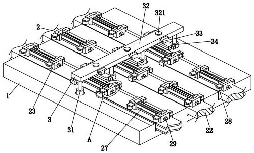
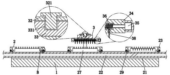
[0032] refer to Figure 1-Figure 7 , a transformer terminal manufacturing molding processing machine, including a workbench 1, a conveying unit 2 and a drilling unit 3, the upper end of the workbench 1 is uniformly provided with a conveying unit 2 from front to back, and the drilling unit 3 is installed on the workbench 1 upper middle.

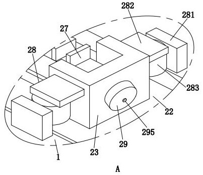
[0033] refer to figure 1 , figure 2 , image 3 , the conveying unit 2 includes a sliding groove 21, an intermittent transmission belt 22, a block 23, a relief groove 24, a linkage hole 25, a locking groove 26, a terminal 27, a positioning assembl...


PUM


Abstract

The invention relates to the technical field of transformer terminal processing, in particular to a transformer terminal manufacturing and forming processing machine and method, wherein the transformer terminal manufacturing and forming processing machine includes a workbench, a conveying unit and a drilling unit, and the upper end of the workbench is from front to The conveying unit is evenly arranged at the back, and the drilling unit is installed in the middle part of the upper end of the workbench; the present invention can solve the following problems: 1. When the worker drills the hole, he cannot effectively limit and fix it, so that the connecting terminal is in the middle of the drilling The lack of stability at the time leads to a deviation between the actual drilling position and the expected drilling position, and the shaking of the terminal can easily cause displacement between the drill bit and the terminal, which is easy to accidentally injure the worker; 2. The worker is aligning the terminal During the drilling process, most of the terminal blocks can only be drilled sequentially, and batch processing cannot be realized, and the drilling positions of the same batch of terminal blocks cannot be guaranteed to be exactly the same.

Description

technical field [0001] The invention relates to the technical field of transformer terminal processing, in particular to a manufacturing and forming processing machine and method for transformer terminal terminals. Background technique [0002] A transformer is a static electrical device used to convert AC voltage and current to transmit AC power. The wires inside the transformer are usually connected through terminals. Terminals refer to an accessory product used to realize electrical connections. The metal sheet inside the insulating plastic has holes evenly opened on its upper end to connect the wires. Generally, when the terminal is manufactured and processed, the upper end needs to be drilled for later use. [0003] In order to save processing costs, some small-scale manufacturers will use manual operation to drill the terminal blocks. The following problems exist in the manufacturing and processing of transformer terminal blocks: 1. When workers drill holes, they canno...

Claims


Application Information

Patent Timeline
Patent Type & Authority Patents(China)
IPC IPC(8): H01R43/16H01F41/00
CPCH01R43/16H01F41/00
Inventor 李国粮陈怡凡
Owner 昌航电气有限公司
Learn More