
Rotational motor

A technology for rotating motors and rotors, applied in the field of rotating electric motors

Pending Publication Date: 2021-09-07
里基哈曼维尼曼
View PDF0 Cites 2 Cited by
  • Summary
  • Abstract
  • Description
  • Claims
  • Application Information

AI Technical Summary

Problems solved by technology

Specifically, since the magnetic polarity of each electromagnet must be repeatedly reversed, current must be continuously supplied to each electromagnet, which is not electrically efficient

Method used


Image

  • Rotational motor
  • Rotational motor
  • Rotational motor

Examples


Embodiment Construction

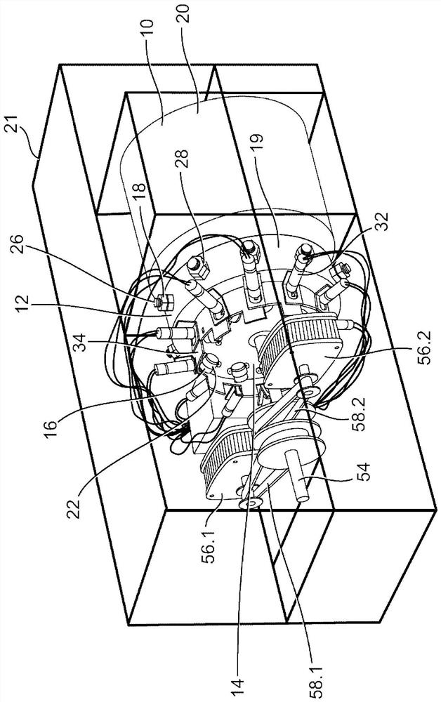
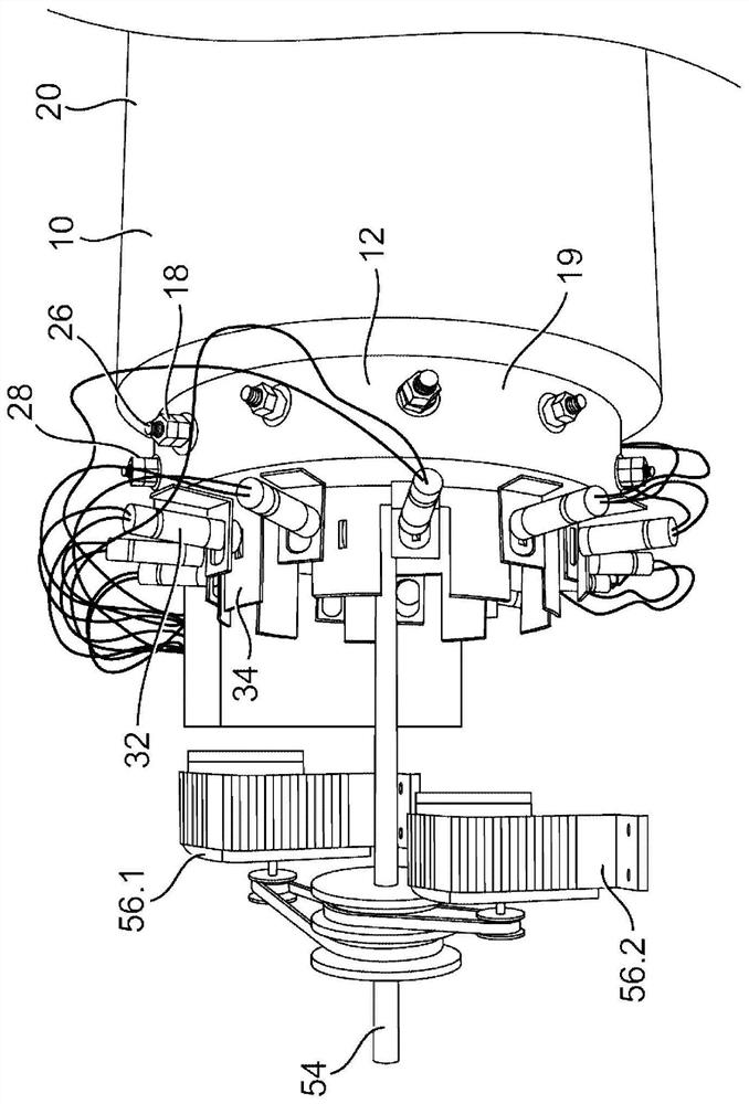
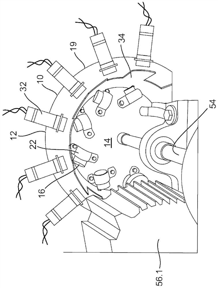
[0043] refer to figure 1 , an example embodiment of the present invention provides a rotary motor 10 comprising a stator 12 and a rotor 14 and at least two magnets including a permanent magnet 16 and an electromagnet 18, wherein one of the magnets is attached Connected to the stator 12 , one of the magnets is attached to the rotor 14 . The magnets 16, 18 are arranged relative to each other such that when the electromagnet 18 is switched off, the permanent magnet 16 is attracted by the ferromagnetic core towards the electromagnet 18 causing the rotor 14 to rotate relative to the stator 12, and when the electromagnet 18 is switched on , the permanent magnet 16 is repelled by the electromagnet 18 , causing the rotor 14 to continue to rotate relative to the stator 12 .

[0044] More specifically, in the example depicted, the stator 12 includes a cylindrical housing 19 provided at one end of a motor block 20 of the rotary motor 10 . The engine block 20 is immovably fixed within a...


PUM


Abstract

A rotational motor that comprises a stator and a rotor and at least two magnets comprising a permanent magnet and an electromagnet, wherein one of the magnets is attached to the stator and one of the magnets is attached to the rotor. The magnets are relatively aligned such that when the electromagnet is switched off, the permanent magnet is attracted to a ferromagnetic core of the electromagnet causing the rotor to rotate relative to the stator, and when the electromagnet is switched on, the permanent magnet is repelled from the electromagnet causing the rotor to continue to rotate relative to the stator.

Description

technical field [0001] This invention relates to electrical engineering, and more particularly, to rotating electric motors. Background technique [0002] Electric motors convert electrical energy into kinetic energy in the form of rotational motion. A direct current (DC) brushed electric motor typically includes a rotating rotor or armature containing electromagnets. A pair of stationary metal brushes, arranged near respective sides of the rotor, make contact with the two rotating poles on the rotor and supply power from the power supply to the electromagnets. The rotating rotor is disposed inside a stationary assembly known as the motor's stator, which typically includes a permanent magnet with a pair of poles. [0003] When current flows through the electromagnets, the magnetic fields created in the rotor attract and repel the two poles of the stator respectively, causing the rotor to turn 180 degrees. As the rotor rotates, each brush makes contact with the opposite el...

Claims


Application Information

Patent Timeline
IPC IPC(8): H02K1/27H02K41/06H02K11/21
CPCH02K21/14H02K1/223H02K33/10H02K99/20H02K49/10H02J3/30H02K7/025H02K16/02
Inventor 里基·哈曼·维尼曼
Owner 里基哈曼维尼曼
Learn More