Stainless steel composite plate automatic forming equipment

A technology for forming equipment and composite panels, applied in welding equipment, non-electric welding equipment, metal processing equipment, etc., can solve the problems of time-consuming and labor-intensive, reduced production efficiency and low efficiency of stainless steel composite panels

Active Publication Date: 2021-09-10
DONGGUAN CITY YUEGANG STAINLESS STEEL PROD
View PDF7 Cites 1 Cited by
  • Summary
  • Abstract
  • Description
  • Claims
  • Application Information

AI Technical Summary

Problems solved by technology

[0004] At present, in the production of stainless steel clad plates by the explosive cladding method, most of them manually superimpose the stainless steel plate and the carbon steel substrate, and then place a mat between the stainless steel plate and the carbon steel substrate, which is time-consuming and laborious, and greatly reduces the stainless steel plate. The production efficiency of the composite board is also mostly manually operated when laying explosives, which is not only inefficient, but also prone to safety hazards. At the same time, manual laying cannot ensure the uniform distribution of explosives, which is likely to affect the composite effect of the stainless steel composite board. This brings inconvenience to the production of stainless steel composite panels

Method used


Image

  • Stainless steel composite plate automatic forming equipment
  • Stainless steel composite plate automatic forming equipment
  • Stainless steel composite plate automatic forming equipment

Examples


Embodiment Construction

[0029] In order to make the technical means, creative features, goals and effects achieved by the present invention easy to understand, the present invention will be further described below in conjunction with specific illustrations. It should be noted that, in the case of no conflict, the embodiments in the present application and the features in the embodiments can be combined with each other.

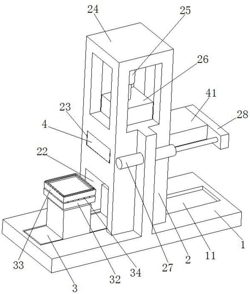
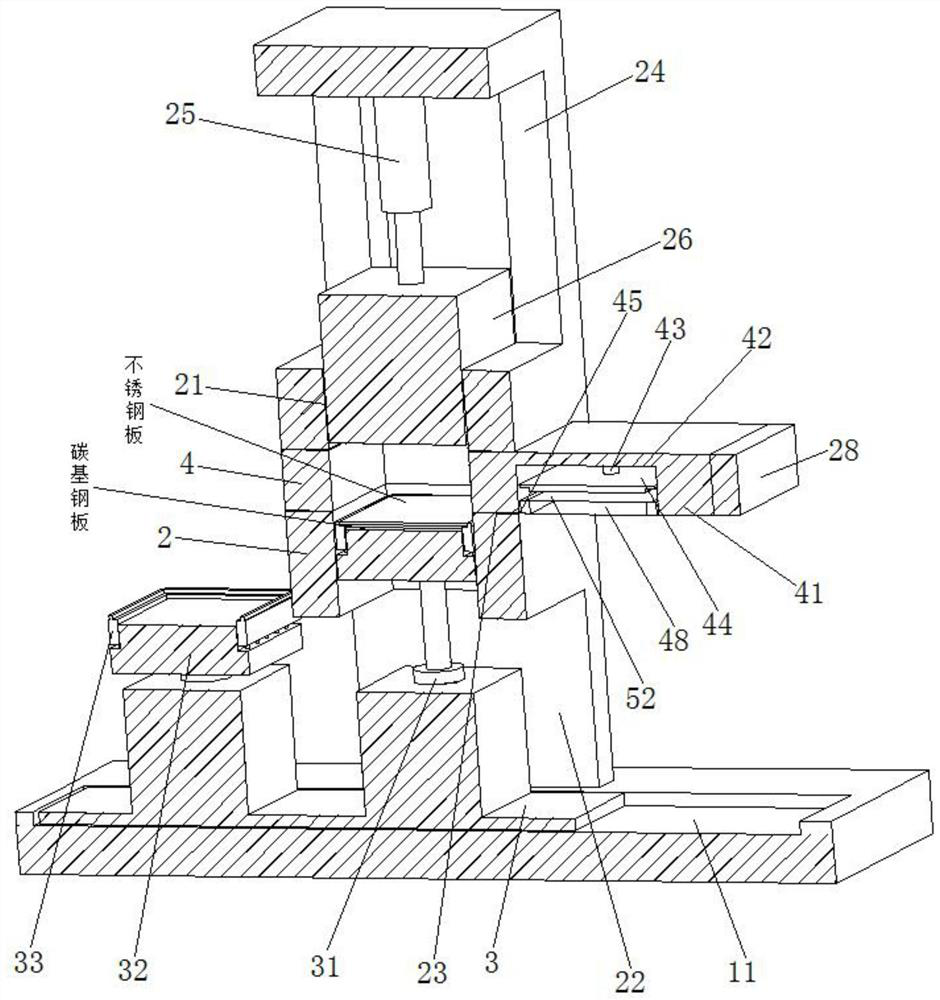
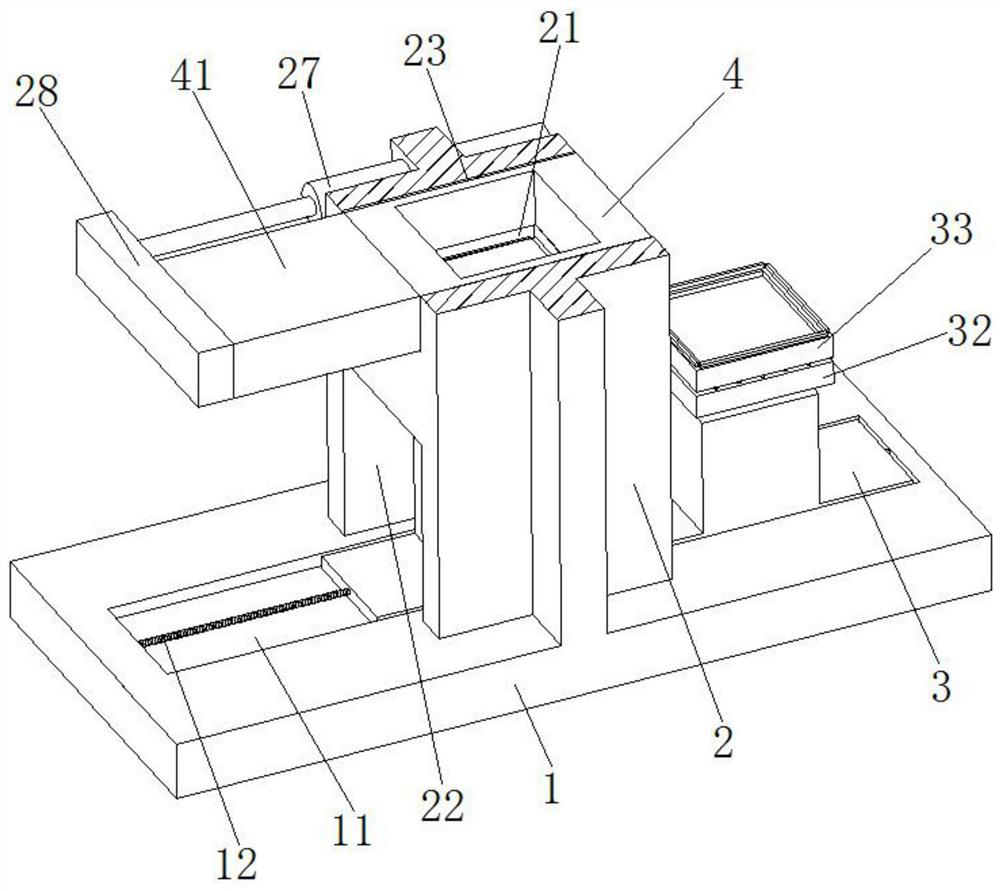
[0030] Such as Figure 1 to Figure 8 As shown, an automatic forming equipment for a stainless steel composite plate includes a base 1, a fixed frame 2 with a rectangular structure is arranged on the base 1, a No. There are No. 2 through groove 22 and No. 3 through groove 23, the two ends of No. 1 through groove 21, No. 2 through groove 22 and No. 3 through groove 23 all run through the fixing frame 2, No. 2 through groove 22 and No. 3 through groove 23 Connect with the No. 1 through groove 21 respectively, the bottom of the No. 3 through groove 23 communicate with the base 1, the ba...


PUM


Abstract

The invention relates to the field of stainless steel plate production, in particular to stainless steel composite plate automatic forming equipment. The equipment comprises a base, a fixing frame of a rectangular structure is arranged on the base, a first through groove of a rectangular structure is vertically formed in the fixing frame, a second through groove and a third through groove are horizontally formed in the fixing frame, the two ends of the first through groove, the two ends of the second through groove and the two ends of the third through groove all penetrate through the fixing frame, the second through groove and the third through groove communicate with the first through groove, the bottom of the third through groove communicates with the base, a sliding groove is formed in the position, located below the second through groove, of the base, a movable frame is slidably installed in the sliding groove, the movable frame is inserted in the second through groove, first air cylinders are symmetrically arranged on the movable frame, and bottom plates of inverted-T-shaped structures are arranged at the output ends of the first air cylinders. A stainless steel plate and a carbon steel base plate can be rapidly positioned and separated, meanwhile, explosive can be automatically laid on the positioned stainless steel plate, and the equipment is suitable for popularization.

Description

technical field [0001] The invention relates to the field of stainless steel plate production, in particular to automatic forming equipment for stainless steel composite plates. Background technique [0002] The stainless steel clad plate is a clad steel plate made of a carbon steel base and a stainless steel cladding. Its main feature is that carbon steel and stainless steel form a strong metallurgical bond. It can be processed by hot pressing, cold bending, cutting, welding, etc., and has good process performance. [0003] Conventional stainless steel clad plate production and processing methods mainly include two methods, explosive cladding and hot rolling cladding, among which the explosive cladding method is the more commonly used one, mainly overlapping stainless steel plates on carbon steel substrates, stainless steel plates and carbon steel plates There is a certain distance between the steel substrates with cushions. Explosives are laid flat on the stainless stee...

Claims


Application Information

Patent Timeline
Patent Type & Authority Applications(China)
IPC IPC(8): B23K20/08B23K20/16B23K20/26B23K101/18B23K103/04
CPCB23K20/08B23K20/165B23K20/26B23K2101/18B23K2103/05
Inventor 王海平
Owner DONGGUAN CITY YUEGANG STAINLESS STEEL PROD
Why Eureka
Try Eureka