Quick change device for machining blade tip center hole of die forging blade

A center hole and vane technology, applied in the field of quick change devices, can solve problems such as inconsistent positions

Pending Publication Date: 2021-09-10
AECC AVIATION POWER CO LTD
View PDF8 Cites 2 Cited by
  • Summary
  • Abstract
  • Description
  • Claims
  • Application Information

AI Technical Summary

Problems solved by technology

[0004] Aiming at the problem in the prior art that similar die-forging blades have inconsistent positions when they are clamped in the fixture, the present invention provides a quick-change device for processing the center hole

Method used


Image

  • Quick change device for machining blade tip center hole of die forging blade
  • Quick change device for machining blade tip center hole of die forging blade
  • Quick change device for machining blade tip center hole of die forging blade

Examples


Embodiment Construction

[0034] The present invention will be further described in detail below in conjunction with the accompanying drawings, which are explanations rather than limitations of the present invention.

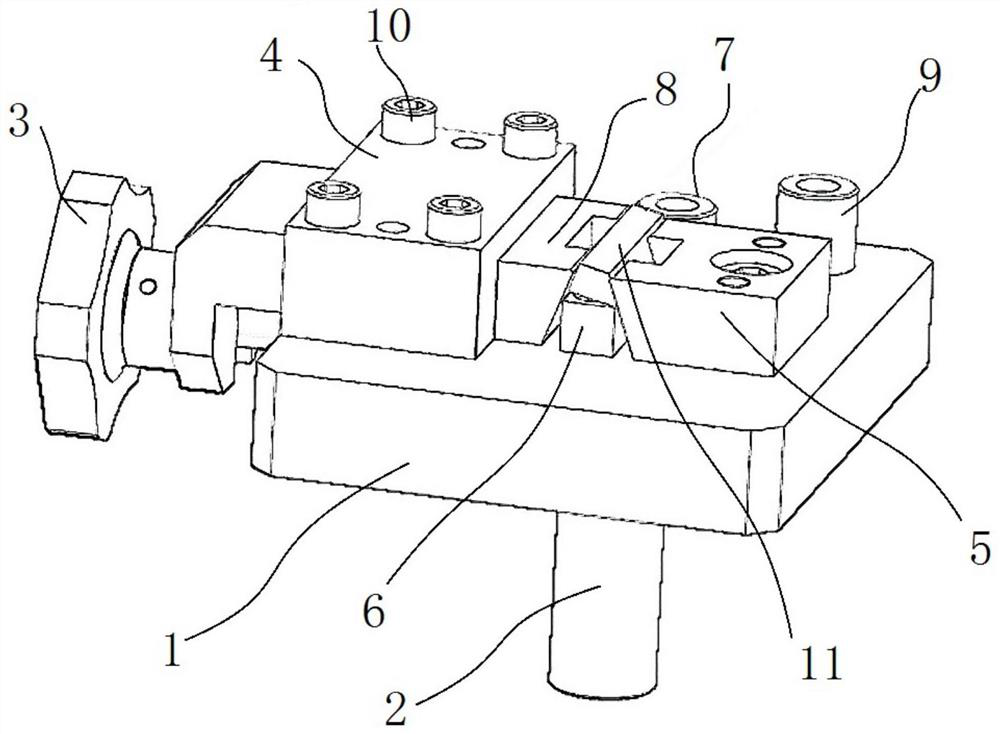
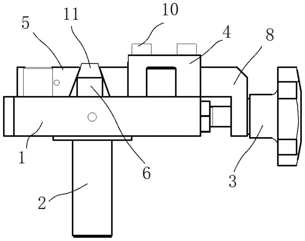
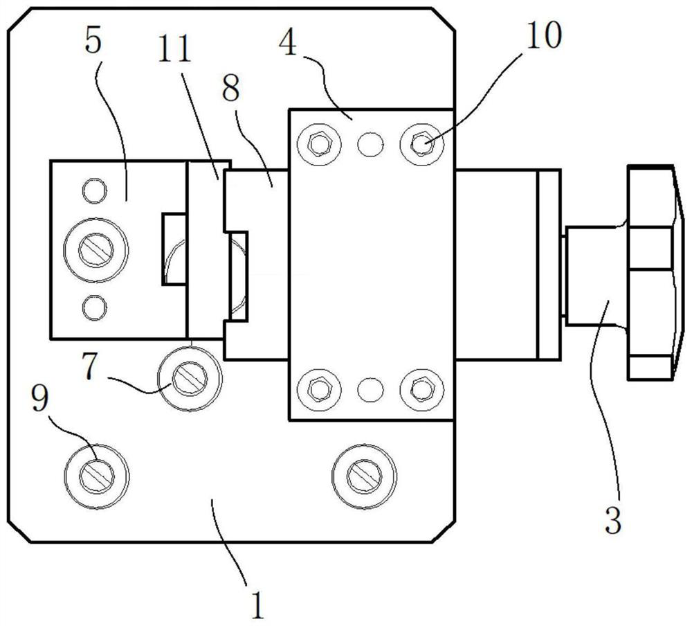
[0035] The invention provides a quick-change device for machining the center hole of the tip of a die-forged blade, comprising figure 1 , figure 2 and image 3 As shown, it includes the body of the quick-change device for clamping the tenon part 11 of the forged blade test piece; the body of the quick-change device includes the clamping bottom plate 1, the positioning mandrel 2 and the clamping assembly;

[0036] The clamping base plate 1 is provided with a through hole, the clamping assembly is assembled on the top surface of the clamping base plate 1, and the positioning mandrel 2 is inserted into the through hole and fixedly connected to the bottom surface of the clamping base plate 1;

[0037] The clamping assembly includes a blade limiting assembly and a blade clamping part 8; th...


PUM


Abstract

The invention provides a quick change device for machining a blade tip center hole of a die forging blade. A clamping assembly is assembled on the top face of a clamping bottom plate, a positioning mandrel is assembled on the bottom face of the clamping bottom plate, and the tenon part of a die forging blade test piece is aligned and clamped. The device only position the tenon part of the die forging blade test piece, the positioning difference of profile of a raw state blade body is avoided, meanwhile, the position of the tenon part of the die forging blade test piece corresponds to the positioning mandrel, so that the consistency of part clamping and positioning is improved, a quick-change mechanism is conveniently formed in the machining process of similar parts, and the machining time is shortened.

Description

technical field [0001] The invention relates to the technical field of die-forging blade processing of aero-engines, in particular to a quick-change device for processing a center hole of a blade tip of a die-forging blade. Background technique [0002] The blade is a very important type of aero-engine parts, which plays a key role in the performance of the engine. The shape of the blade is irregular, which is very different from ordinary parts. Therefore, the processing and manufacturing of the blade and its quality are very important to the aero-engine. For blades whose forgings are die forgings, there is a large machining allowance for the blade body and the tenon. The processing technology of the parts is arranged in sequence: milling, exhaust edge, CNC milling tenon, center hole drilling, and CNC milling surface , intake and exhaust edges and edge plates. [0003] The process of drilling the center hole is the process benchmark for the subsequent processing of the airf...

Claims


Application Information

Patent Timeline
IPC IPC(8): B23Q3/00
CPCB23Q3/00
Inventor 种妮蒲海龙贾帅侯飞龙张义德周经纬豆雷红王伟涛
Owner AECC AVIATION POWER CO LTD
Why Eureka
Try Eureka