
Disassembling jig

A jig and carrier technology, which is applied in the direction of hand-held tools, manufacturing tools, workpiece clamping devices, etc., can solve the problems of increasing the difficulty of disassembly, unstable fixing of the carrier, and unstable fixation, etc.

Active Publication Date: 2021-09-10
JIANGSU CHUANGYUAN ELECTRON CO LTD
View PDF11 Cites 2 Cited by
  • Summary
  • Abstract
  • Description
  • Claims
  • Application Information

AI Technical Summary

Problems solved by technology

[0003] However, when the existing dismantling jig fixes the carrier on which the watch is placed, the carrier is clamped and fixed only through the carrier assembly and the cover assembly. Due to certain processing errors in the carrier assembly and the cover assembly, The carrier is not fixed firmly between the carrier component and the cover plate component. When the operator disassembles the watch in the carrier, the carrier or the watch is prone to shaking, which increases the difficulty of disassembly.
[0004] Therefore, there is an urgent need to invent a dismantling jig to solve the problem that the carrier is not firmly fixed between the carrier assembly and the cover assembly, and when the watch in the carrier is disassembled, the carrier or the watch is prone to shaking.

Method used


Image

  • Disassembling jig
  • Disassembling jig
  • Disassembling jig

Examples


Embodiment Construction

[0050] In order to make the technical problems solved by the present invention, the technical solutions adopted and the technical effects achieved clearer, the technical solutions of the present invention will be further described below in conjunction with the accompanying drawings and through specific implementation methods.

[0051] In the description of the present invention, unless otherwise clearly specified and limited, the terms "connected", "connected" and "fixed" should be understood in a broad sense, for example, it can be a fixed connection, a detachable connection, or an integrated ; It can be a mechanical connection or an electrical connection; it can be a direct connection or an indirect connection through an intermediary, and it can be the internal communication of two components or the interaction relationship between two components. Those of ordinary skill in the art can understand the specific meanings of the above terms in the present invention in specific si...


PUM


Abstract

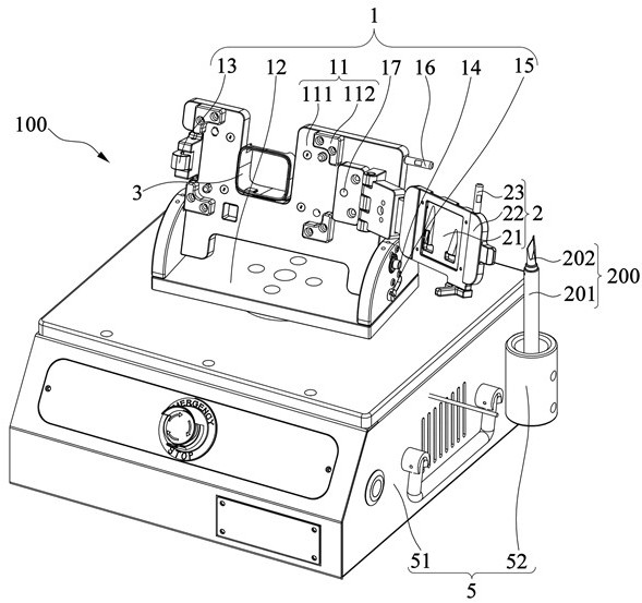
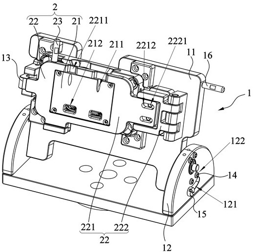
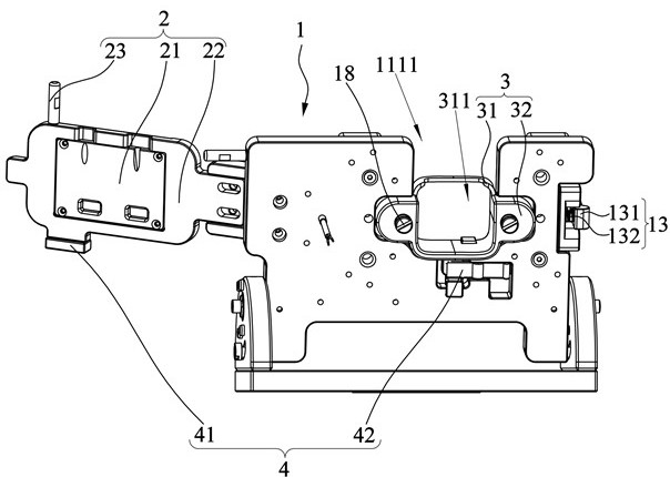
The invention relates to the technical field of disassembling of electronic equipment, and particularly relates to a disassembling jig. The disassembling jig comprises a bearing assembly, a clamping assembly and a cover plate assembly, the bearing assembly is used for bearing a carrier containing a to-be-disassembled part, the clamping assembly is movably connected with the bearing assembly, the cover plate assembly is rotatably connected with the bearing assembly, and when the cover plate assembly and the bearing assembly are in a locked state, the cover plate assembly and the clamping assembly jointly clamp the carrier and the to-be-disassembled part. When an operator disassembles the to-be-disassembled part in the carrier, the carrier and the to-be-disassembled part can be prevented from shaking so that the carrier and the to-be-disassembled part are stably fixed, and accurate disassembling of the to-be-disassembled part is guaranteed.

Description

technical field [0001] The invention relates to the technical field of electronic equipment disassembly, in particular to a disassembly jig. Background technique [0002] Parts in electronic equipment (smart watches) are difficult and time-consuming to repair and disassemble. In order to prevent damage to the parts in the watch during manual disassembly. Most of the existing technologies use semi-automatic dismantling jigs for assistance. By fixing the carrier on which the watch is placed on the dismantling jig, the watch is then disassembled to ensure that the watch is firmly fixed during the dismantling process. [0003] However, when the existing dismantling jig fixes the carrier on which the watch is placed, the carrier is clamped and fixed only through the carrier assembly and the cover assembly. Due to certain processing errors in the carrier assembly and the cover assembly, The carrier is not firmly fixed between the carrier assembly and the cover assembly. When the ...

Claims


Application Information

Patent Timeline
IPC IPC(8): B25B11/02B25B27/00
CPCB25B11/02B25B27/00
Inventor 刘宏波
Owner JIANGSU CHUANGYUAN ELECTRON CO LTD
Learn More