Industrial robot arm capable of doing linear motion

An industrial robot, linear technology, applied in the direction of manipulator, program control manipulator, claw arm, etc., can solve the problem of unloading and other problems

Inactive Publication Date: 2021-09-10
陈春莉
View PDF0 Cites 5 Cited by
  • Summary
  • Abstract
  • Description
  • Claims
  • Application Information

AI Technical Summary

Problems solved by technology

[0010] The purpose of the present invention is to provide an industrial robot arm capable of linear motion, so as to solve the problem in the above-...

Method used


Image

  • Industrial robot arm capable of doing linear motion
  • Industrial robot arm capable of doing linear motion
  • Industrial robot arm capable of doing linear motion

Examples


Embodiment 1

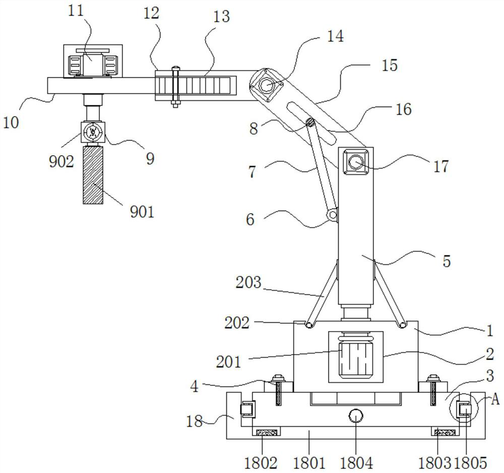
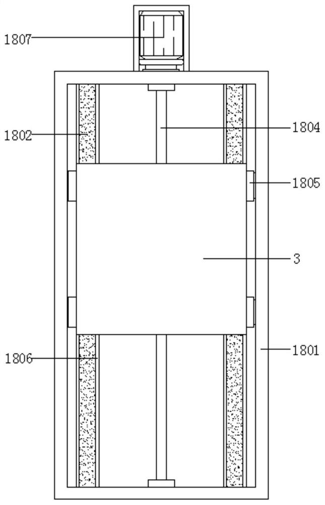
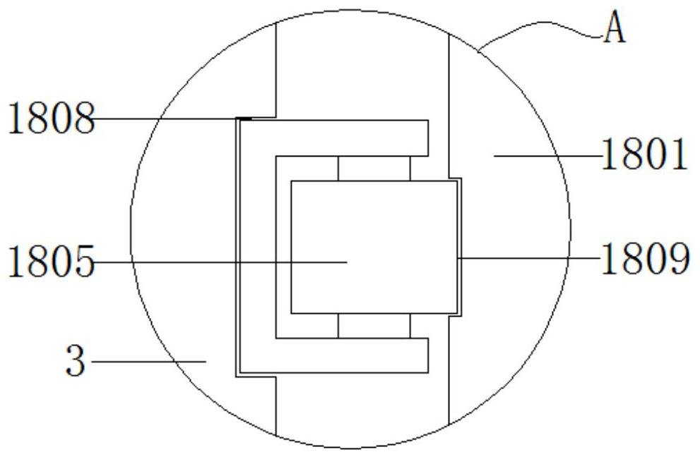
[0042] Embodiment 1: An industrial robot arm capable of linear motion, including a base 1, a mounting base 3 and a support column 5, the bottom of the mounting base 3 is provided with a moving mechanism 18, and the moving mechanism 18 includes a rectangular frame 1801, a slide rail 1802, slide block 1803, screw rod 1804, roller 1805, rectangular groove 1806, low-speed motor 1807, mounting groove 1808 and chute 1809; the bottom of mounting seat 3 is provided with rectangular frame body 1801, and the inner two sides of rectangular frame body 1801 are provided with Rectangular groove 1806, the interior of rectangular groove 1806 is fixed with slide rail 1802, and the outer wall of slide rail 1802 is slidably connected with four sets of sliders 1803, and the outer wall of four sets of sliders 1803 is fixedly connected with the bottom of mounting base 3, four sets of sliders 1803 is fixedly connected to the bottom corner of the mounting base 3; the middle part of the bottom end of t...

Embodiment 2

[0044] Example 2: see Figure 1-10 , the base 1 is set on the top of the mounting base 3, a structure 4 for facilitating stable assembly is provided between the base 1 and the mounting base 3, the support column 5 is movably connected to the top of the base 1, and the bottom end of the support column 5 is provided with a stable rotation mechanism 2. The top of the support column 5 is hinged with a second movable arm 15, and the top of the front end of the support column 5 is fixedly connected with a second rotary cylinder 17. The type of the second rotary cylinder 17 can be MSQB10, and the top of the second movable arm 15 is movable The first movable arm 12 is hinged, and the top of the front end of the second movable arm 15 is fixedly connected with the first rotary cylinder 14. The model of the first rotary cylinder 14 can be MSQB20. One side of the first movable arm 12 is provided with a horizontal plate 10. One side of the top of the horizontal plate 10 is fixedly connecte...

Embodiment 3

[0048] Embodiment 3: The stable rotation mechanism 2 is composed of a driving motor 201, a rolling groove 202, a stabilizing bar 203, a movable groove 204 and a ball 205. The driving motor 201 is fixedly connected to the inside of the base 1. The model of the driving motor 201 can be Y80M2-2 , the stabilizer bar 203 is fixedly connected to the outside of the support column 5 at a position near the bottom end, the rolling groove 202 is arranged inside the top of the base 1, the inside of the bottom end of the stabilizer bar 203 is provided with a movable groove 204, and the inside of the movable groove 204 is provided with a ball 205;

[0049] There are six sets of stabilizing rods 203 outside the support column 5, and the bottom ends of the stabilizing rods 203 are embedded in the inside of the rolling groove 202;

[0050] Specifically, such as figure 1 , Figure 5 and Figure 8 As shown, when in use, the driving motor 201 drives the support column 5 to rotate, and at this t...


PUM


Abstract

The invention discloses an industrial robot arm capable of doing linear motion, and relates to the technical field of mechanical arms. The industrial robot arm comprises a base, a mounting seat and a supporting column, wherein a moving mechanism is arranged at the bottom of the mounting seat; and the moving mechanism comprises a rectangular frame body, sliding rails, sliding blocks, a screw rod, rolling wheels, rectangular grooves, a low-speed motor, mounting grooves and sliding grooves. During use of the industrial robot arm capable of doing linear motion, when goods need to be conveyed linearly after being clamped, the low-speed motor is started to drive the screw rod to rotate; the screw rod is in threaded connection with the mounting seat, and the bottom of the mounting seat is slidably connected to the rectangular frame body through the sliding rails and the sliding blocks, so that the mounting seat can perform linear motion; and therefore, the whole mechanism can perform linear motion so as to achieve linear conveying of the goods.

Description

technical field [0001] The invention relates to the technical field of mechanical arms, in particular to an industrial robot arm capable of linear motion. Background technique [0002] On the assembly line of industrial production, it is generally equipped with a robot arm for handling and transferring goods. This kind of robot arm can very well replace the artificial arm, liberate the labor force, and bring considerable economic benefits to industrial production, but now Some industrial robot arms have many problems and defects, so a new type of industrial robot arm is needed. [0003] In the process of realizing the present invention, the inventors have found that at least the following problems in the prior art have not been resolved: [0004] (1) The traditional industrial robot arm has no anti-fall function, and its safety performance is poor when used; [0005] (2) The stability of the traditional industrial robot arm is poor when it rotates, and it is prone to damag...

Claims


Application Information

Patent Timeline
IPC IPC(8): B25J9/00B25J9/04B25J15/08B25J18/02B25J19/00
CPCB25J9/04B25J9/00B25J19/00B25J15/08B25J18/025B25J9/0009
Inventor 陈春莉
Owner 陈春莉
Why Eureka
Try Eureka