Machining jig for motor controller board

A technology of motor controller and jig, applied in metal processing and other directions, can solve the problem of time-consuming and so on

Active Publication Date: 2021-09-10
常州市昌隆电机股份有限公司
View PDF9 Cites 0 Cited by
  • Summary
  • Abstract
  • Description
  • Claims
  • Application Information

AI Technical Summary

Problems solved by technology

However, once the overall circuit board is positioned and sliced, the waste

Method used


Image

  • Machining jig for motor controller board
  • Machining jig for motor controller board
  • Machining jig for motor controller board

Examples


Embodiment Construction

[0039] The present invention is described in further detail now in conjunction with accompanying drawing. These drawings are all simplified schematic diagrams, which only illustrate the basic structure of the present invention in a schematic manner, so they only show the configurations related to the present invention.

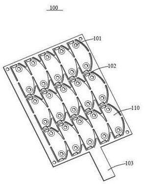
[0040] Generally, during the processing of circuit boards, a whole board will be divided into multiple boards. In the process of separating the boards, the fixing effect of the whole board and the positioning after the formation of multiple boards directly determine the effect of the process. In the prior art, the entire board is usually compacted with the help of external clamps, and there is seldom positioning for multiple boards. Therefore, there is a need for a multi-board positioning fixture for circuit boards.

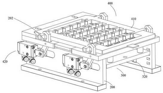
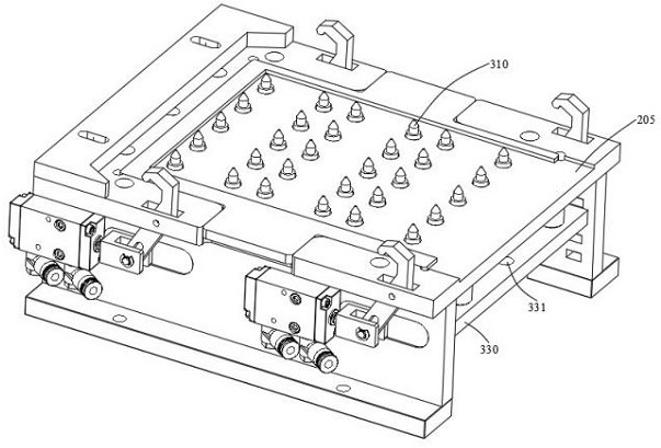
[0041] like Figures 1 to 10 As shown, the present invention provides a jig for a motor controller board, including: a positioning table 200,...


PUM


Abstract

The invention relates to a machining jig for a motor controller board. The machining jig for the motor controller board comprises a positioning table, a lifting limiting part and a compaction part. The positioning table is suitable for bearing a whole circuit board; the lifting limiting part is suitable for lifting and limiting the whole circuit board; the compaction part is suitable for being pressed on the positioning table, an adjustable bin is formed in the side portion of the compaction part, and the adjustable bin can be unfolded and enables the compaction part to abut against the whole circuit board on the positioning table; and after the whole circuit board is cut, the lifting limiting part is pressed until the lifting limiting part is separated from the whole circuit board, and the adjustable bin is unfolded to pull out waste materials and a plurality of circuit board sub-boards. Through the arrangement of the positioning table, the bearing of the whole circuit board is facilitated, through the arrangement of the lifting limiting part, the whole circuit board is lifted and positioned by the lifting limiting part, and through the arrangement of the compaction part, the vertical positioning of the whole circuit board is realized; and the adjustable bin is matched with the lifting limiting part, so that the waste materials and the circuit board sub-boards are taken out and placed under an action of not opening the compaction part.

Description

technical field [0001] The invention relates to motor processing equipment, in particular to a processing jig for a motor controller board. Background technique [0002] During the general processing of circuit boards, a whole board will be divided into multiple boards. In the process of separating the boards, the fixing effect of the whole board and the positioning after the formation of multiple boards directly determine the effect of the process. [0003] Generally, the entire board is usually compacted by means of external clamps, and there is seldom the positioning of multiple boards. However, once the whole circuit board is positioned and sliced, the waste material needs to be disassembled, and the disassembly process takes a lot of time. Contents of the invention [0004] The technical problem to be solved in the present invention is: to overcome the technical problem in the prior art, the technical solution adopted by the present invention to solve the technical ...

Claims


Application Information

Patent Timeline
IPC IPC(8): B26D7/02B26D7/04B26D7/18B26D7/22
CPCB26D7/04B26D7/18B26D7/22B26D7/025B26D7/1836
Inventor 王建南高昱黄丽萍王璐颖
Owner 常州市昌隆电机股份有限公司
Why Eureka
Try Eureka