New energy automobile charging pile with heat dissipation and rainproof functions
A new energy vehicle, charging pile technology, applied in electric vehicle charging technology, charging station, electric vehicle and other directions, can solve the problems of affecting the service life, low safety, no heat dissipation function, etc.
- Summary
- Abstract
- Description
- Claims
- Application Information
AI Technical Summary
Problems solved by technology
Method used
Image
Examples
Embodiment 1
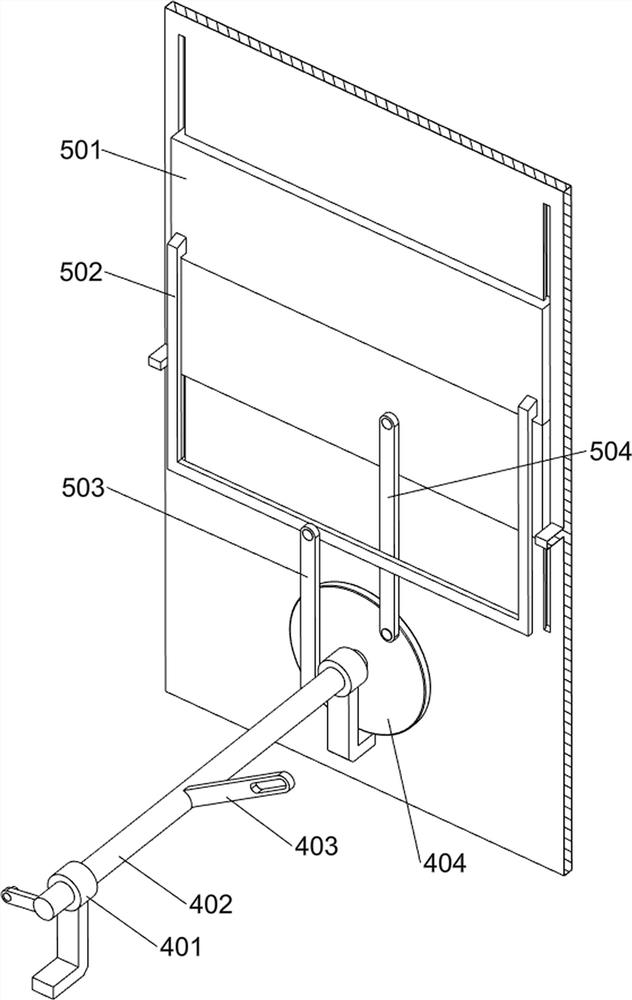
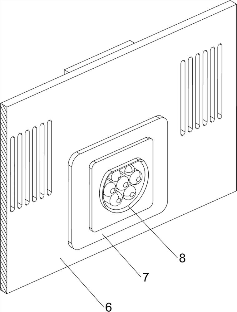
[0035] A new energy vehicle charging pile with heat dissipation and rainproof functions, such as figure 1 , figure 2 , image 3 , Figure 6 , Figure 7 , Figure 8 and Figure 9 As shown, it includes a bracket 1, a first housing 2, a pedal assembly 3, a rotating assembly 4, an opening and closing assembly 5, a partition 6, a charging module 7, a power cord 701, an indicator light 702, a socket 8 and a cooling assembly 10 , the top of the bracket 1 is connected with the first housing 2, the pedal assembly 3 is installed on the bracket 1, the rotation assembly 4 is installed in the lower part of the first housing 2, the opening and closing assembly 5 is installed in the upper part of the first housing 2, the second A partition 6 is vertically connected to the upper part of the casing 2, a charging module 7 is installed on the lower part of the partition 6, a power line 701 is connected to the middle of the rear side of the charging module 7, an indicator light 702 is insta...
Embodiment 2
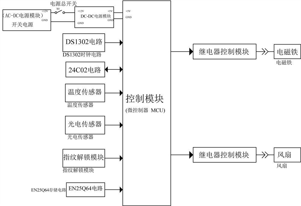
[0042] On the basis of Example 1, such as figure 1 , Figure 4 , Figure 5 , Figure 7 , Figure 8 , Figure 10 , Figure 11 and Figure 12 As shown, a locking assembly 11 is also included. The locking assembly 11 includes a lever 1101, an electromagnet 1102, a second spring 1103, a second housing 1105, a photoelectric sensor 1106 and a fingerprint recognition module 1107. The inner bottom of the first housing 2 The sliding type is provided with a clamping rod 1101, which is made of iron. An electromagnet 1102 is installed on the inner bottom of the first housing 2. The electromagnet 1102 is located on the front side of the clamping rod 1101. The second spring 1103 is connected between them, the upper and lower sides of the front side of the sliding bar 303 are provided with card slots 1104, the card bar 1101 is located in the lower card slot 1104, and the middle of the top of the charging module 7 is connected with a second housing 1105, indicating The lamp 702 is loca...
PUM
 Abstract
Description
Claims
Application Information
 - R&D
- Intellectual Property
- Life Sciences
- Materials
- Tech Scout
- Unparalleled Data Quality
- Higher Quality Content
- 60% Fewer Hallucinations
Browse by: Latest US Patents, China's latest patents, Technical Efficacy Thesaurus, Application Domain, Technology Topic, Popular Technical Reports.
© 2025 PatSnap. All rights reserved.Legal|Privacy policy|Modern Slavery Act Transparency Statement|Sitemap|About US| Contact US: help@patsnap.com


