Unmanned aerial vehicle for water sample collection

A technology for drones and water samples, applied in the field of drones, can solve the problems of inaccurate sampling location, low efficiency, and inconvenience

Active Publication Date: 2021-09-10
深圳市华芯机器人技术有限责任公司
View PDF8 Cites 0 Cited by
  • Summary
  • Abstract
  • Description
  • Claims
  • Application Information

AI Technical Summary

Problems solved by technology

[0003] However, this water quality sampling method has problems such as inconvenience, low efficiency, and inaccurate sampling positions. Therefore, in the prior art, UAVs are usually used for water sample collection. The existing collection method is usually suspended under the UAV. The sampling cylinder controls the drone to fly above the sampling point, and then controls the drone to descend and make the sampling cylinder enter the water for sampling. However, in some lakes, there are usually a large number of aquatic plants and floating discs floating on the water surface. When sampling, the sampling cylinder will not be able to enter the water for sampling due to the influence of aquatic plants and other debris, making sampling extremely inconvenient

Method used


Image

  • Unmanned aerial vehicle for water sample collection
  • Unmanned aerial vehicle for water sample collection
  • Unmanned aerial vehicle for water sample collection

Examples


Embodiment 1

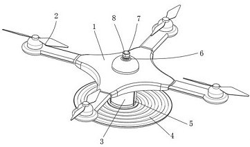
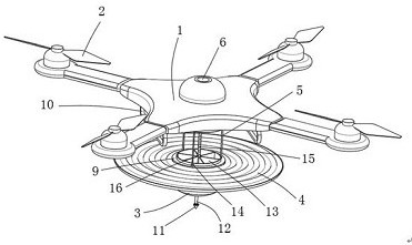
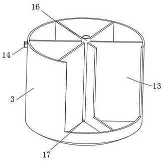
[0030] refer to Figure 1-8 , an unmanned aerial vehicle for water sample collection, comprising a casing 1, the four corners of the casing 1 are provided with wings 2, the inside of the casing 1 is provided with a controller 36, and the bottom outer wall of the casing 1 is provided with a frame 10, The bottom of the casing 1 is provided with a collection tube 3, and the bottom surface of the collection tube 3 is a spherical structure. There are at least six annular partitions 13 that are evenly distributed in fixed connection, and there is a collection chamber between every two partitions 13. The side inner wall of the casing 1 above the middle cylinder 16 is provided with an intermediate shell 6 that penetrates the casing 1. And the inside of the middle shell 6 is provided with a lifting mechanism, the bottom of the middle cylinder 16 penetrates the bottom of the collection cylinder 3 , and the inside of the middle cylinder 16 is provided with a rotating collection mechanism...

Embodiment 2

[0038] refer to Figure 9 and Figure 10 , on the basis of Embodiment 1, the boom 5 is a hollow shell structure, and the side inner wall of the boom 5 is fixedly connected with a compressed air tank 39, and the inside of the compressed gas tank 39 is filled with compressed air 40, and the compressed gas tank The bottom end of 39 is connected with air guide pipe 41, and the side outer wall of air guide pipe 41 is provided with electromagnetic valve 42, is provided with gravity acceleration sensor in controller 36;

[0039] The floating plate 4 includes a floating plate 37 and an air bag 38 bonded to the top of the floating plate 37. The bottom outer wall of the bottom ring 9 has a circular hole, and one end of the air duct 41 extends to the inside of the circular hole. The top of the floating plate 4 is fixedly connected with Insert the cannula 43 inside the circular hole, and the cannula 43 is connected by the air bag 38 .

[0040] Wherein, the bottom outer wall of the casin...


PUM


Abstract

The invention belongs to the technical field of unmanned aerial vehicles, particularly relates to an unmanned aerial vehicle for water sample collection, and provides the following scheme for solving the problems in the prior art: the unmanned aerial vehicle comprises a machine shell, wings are arranged at four corners of the machine shell, a controller is arranged in the machine shell, a rack is arranged on the outer wall of the bottom of the machine shell, and a collection barrel is arranged below the machine shell; the bottom face of the collection barrel is of a spherical surface structure, a middle barrel is fixedly connected to the inner wall of the bottom of the collection barrel, at least six annularly and evenly distributed partition plates are fixedly connected between the outer wall of the side face of the middle barrel and the inner wall of the side face of the collection barrel, and a collection cavity is reserved between every two partition plates. A middle shell penetrating through the machine shell is arranged on the inner wall of the side face, located on the middle cylinder, of the machine shell, and a pressure lifting mechanism is arranged in the middle shell. The unmanned aerial vehicle prevents impurities such as duckweed on the water surface from influencing water sample collection, can ensure that no large impurities exist in the collected water sample, and facilitates subsequent cleaning.

Description

technical field [0001] The invention relates to the technical field of unmanned aerial vehicles, in particular to an unmanned aerial vehicle for collecting water samples. Background technique [0002] With the rapid development of society, people pay more and more attention to environmental protection issues, and the environmental monitoring and protection of water resources is the most important among them. The collection of water samples in water areas is an important task in the monitoring of water resources and environment. In the past, it was necessary to charter a boat to drive to various locations in the water area, manually throw the water collector into the water for water sample collection, and then transport the collected water samples back to the At the shore workstation, the staff will conduct water quality testing on water samples. [0003] However, this water quality sampling method has problems such as inconvenience, low efficiency, and inaccurate sampling p...

Claims


Application Information

Patent Timeline
Patent Type & Authority Applications(China)
IPC IPC(8): B64C27/08B64C39/02B64D47/00G01N1/10
CPCB64C27/08B64C39/024B64D47/00G01N1/10B64U10/10B64U2101/00
Inventor 魏旭平
Owner 深圳市华芯机器人技术有限责任公司
Why Eureka
Try Eureka