Pile foundation pouring system for building

A technology for construction and pile foundation, applied in construction, sheet pile wall, foundation structure engineering, etc., can solve the problems of reduced pile foundation stability, high difficulty in placing, and reduced bearing capacity.

Inactive Publication Date: 2021-09-10
刘凤华
View PDF0 Cites 0 Cited by
  • Summary
  • Abstract
  • Description
  • Claims
  • Application Information

AI Technical Summary

Problems solved by technology

[0002] As we all know, in the foundation construction, a large number of pile foundation projects will be involved. Before the pile foundation concrete is injected, in order to protect the steel cage, a steel casing will be put into the dug pile hole first, and then a crane will be used to put it into the steel casing coaxial with the steel casing. The reinforcement cage is difficult to put in and takes a long time, and then the concrete is injected. With the injection of concrete, the reinforcement cage will be floated up by the buoyancy force. In order to ensure that the reinforcement cage will not move too much and the stability of the pile foundation, it is necessary to reduce the reinforcement The more serious the floating of the cage, the more serious the floating of the steel cage, the more serious the adverse effect on the quality of the pile. At the same time, with the injection of the lower layer of concrete, the pressure on the lower end of the steel cage is gradually increased, and the steel cage is easy to bend and deform under pressure, reducing its own bearing capacity. force, which reduces the stability of the pile foundation

Method used


Image

  • Pile foundation pouring system for building
  • Pile foundation pouring system for building
  • Pile foundation pouring system for building

Examples


Embodiment Construction

[0024] The following are specific embodiments of the present invention and in conjunction with the accompanying drawings, the technical solutions of the present invention are further described, but the present invention is not limited to these embodiments.

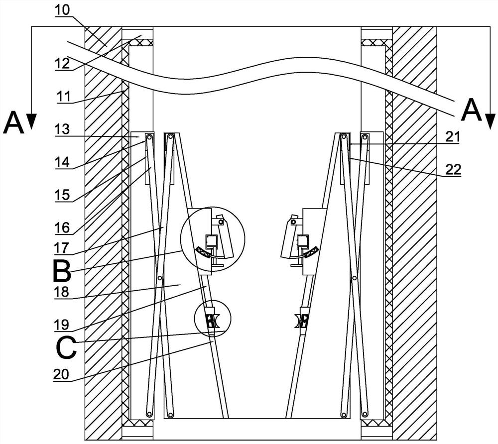
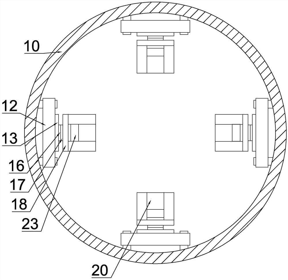
[0025] Such as figure 1 As shown, a building pile foundation pouring system includes a steel casing wall 10, and the inner wall of the steel casing wall 10 is provided with four detachable bolt holes 12 that can be connected by bolts and nuts, and each bolt hole 12 is fixed Lifting grooves 11 are provided, and lifting slides 13 are arranged to slide up and down in the lifting grooves 11. Each lifting slide 13 is provided with a size adapting device, and the size adapting device is used to adjust the distance with the steel cage.

[0026] Such as figure 1 with figure 2 As shown, the size adaptation device includes a hinge block groove 15 arranged on the end surface of each lifting slide 13 close to the center of the stee...


PUM


Abstract

The invention belongs to the related field of pile foundations, and relates to a pile foundation pouring system for a building. The system comprises a steel casing wall, four detachable bolt holes capable of being connected through bolts and nuts are formed in the inner wall of the steel casing wall, a lifting groove is fixedly formed in each bolt hole, and a lifting sliding plate is arranged in each lifting groove in an up-down sliding manner. A size adapting device is arranged on each lifting sliding plate. The system is detachably mounted on a steel casing, is placed into a drill hole together with the steel casing, and is used for assisting in placing of a reinforcement cage, ensuring that the reinforcement cage and a steel casing are coaxial, protecting the reinforcement cage from floating due to buoyancy in the concrete injection process, and hooping the lower layer of the reinforcement cage by utilizing the floating buoyancy, therefore, the structure of the reinforcement cage is prevented from being damaged by pressure, the working efficiency during pile foundation drilling is improved, the reinforcement cage is protected, and the stability of a pile foundation is improved.

Description

technical field [0001] The invention belongs to the related field of pile foundations, in particular to a pile foundation pouring system for construction. Background technique [0002] As we all know, in the foundation construction, a large number of pile foundation projects will be involved. Before the pile foundation concrete is injected, in order to protect the steel cage, a steel casing will be put into the dug pile hole first, and then a crane will be used to put it into the steel casing coaxial with the steel casing. The reinforcement cage is difficult to put in and takes a long time, and then the concrete is injected. With the injection of concrete, the reinforcement cage will be floated up by the buoyancy force. In order to ensure that the reinforcement cage will not move too much and the stability of the pile foundation, it is necessary to reduce the reinforcement The more serious the floating of the cage, the more serious the floating of the steel cage, the more se...

Claims


Application Information

Patent Timeline
Patent Type & Authority Applications(China)
IPC IPC(8): E02D15/04E02D5/34E02D5/68E02D27/12
CPCE02D15/04E02D5/34E02D5/68E02D27/12
Inventor 不公告发明人
Owner 刘凤华
Why Eureka
Try Eureka