
Trigger type sliding sleeve opening and closing tool

A sliding sleeve switch and trigger technology, which is applied in wellbore/well components, earth-moving drilling, sealing/packing, etc. Improvement of work efficiency, difficulties in work, etc.

Active Publication Date: 2021-09-10
HUNAN VICTOR PETROTECH SERVICE
View PDF13 Cites 2 Cited by
  • Summary
  • Abstract
  • Description
  • Claims
  • Application Information

AI Technical Summary

Problems solved by technology

A large part of the problem is that the sliding sleeve limits the outer diameter of the matching switch tool, so that the diameter of the upper oil pipe must meet the requirements for the smooth passage of the switch tool
However, in the case where the passage of the oil pipe must be narrowed due to the electric submersible pump, double channel or other reasons, ordinary switch tools cannot meet the operation requirements, the operation is difficult, or the operation risk is increased
[0003] Systematic research on the technology of sliding sleeve switch tools at home and abroad, all kinds of sliding sleeve switch tools that can perform switching operations at designated positions require a certain diameter step to start, which cannot fully realize the working environment of small up and down big, and cannot effectively reduce risk, which is not conducive to the improvement of the reliability and efficiency of the entire well completion operation

Method used


Image

  • Trigger type sliding sleeve opening and closing tool
  • Trigger type sliding sleeve opening and closing tool
  • Trigger type sliding sleeve opening and closing tool

Examples


Embodiment Construction

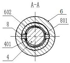
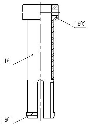
[0028] See figure 1 — Figure 4 , the trigger type sliding sleeve switch tool provided by the present invention, its external dimensions: the maximum diameter is at least 20mm, the length is at least 200mm, including a rod-shaped body, a lock that can be radially and elastically expanded fixedly sleeved on the rod-shaped body The block assembly and the movable sleeve are set on the rod-shaped body and the conical sleeve 9 that axially cooperates with the lock block assembly to limit the radial expansion of the lock block assembly, the thrust spring 10 arranged between the lock block assembly and the conical sleeve 9, and the movable The slider 8 that can move radially on the rod-shaped body and axially restricts the upward movement of the tapered sleeve 9, and the slider 8 that can be movably sleeved on the rod-shaped body and temporarily fixed by elastic positioning components can limit the radial movement of the slider 8 Weighting assembly; when the elastic positioning part...


PUM


Abstract

The invention discloses a trigger type sliding sleeve opening and closing tool. The trigger type sliding sleeve opening and closing tool comprising a rod-shaped body, a locking block assembly fixedly arranged on the rod-shaped body in a sleeving mode and capable of being elastically opened in the radial direction, a conical sleeve movably arranged on the rod-shaped body in a sleeving mode and matched with the locking block assembly in the axial direction to limit radial opening of the locking block assembly, a thrust spring arranged between the locking block assembly and the conical sleeve, a sliding block movably arranged on the rod-shaped body and capable of moving in the radial direction and axially limits upward movement of the conical sleeve, and a weighting assembly movably arranged on the rod-shaped body in a sleeving mode, temporarily fixed through an elastic positioning component and capable of limiting radial movement of the sliding block; and when an elastic positioning part is stressed to relieve positioning of the weighting assembly, the weighting assembly moves upwards to release limitation on the sliding block, the conical sleeve is pushed by the thrust spring to move upwards to release limitation on the locking block assembly, and the locking block assembly is elastically opened. According to the tool, after passing through a small-diameter channel, the tool can be opened at a designated position, and opening and closing operation is conducted on a lower sliding sleeve with the large-diameter opening and closing requirement.

Description

technical field [0001] The invention belongs to a sliding sleeve switch tool in the field of oil and gas exploitation, in particular to a trigger type sliding sleeve switch tool. Background technique [0002] In modern oil and gas extraction, the application of sliding sleeves is very common in the oil and gas extraction process, but in the actual extraction process, various problems are still encountered. A large part of the problem is that the sliding sleeve limits the outer diameter of the supporting switch tool, so that the diameter of the upper oil pipe must meet the requirements for the smooth passage of the switch tool. However, when the oil pipe channel must be narrowed due to the electric submersible pump, dual channels or other reasons, the common switch tool cannot meet the operation requirements, the operation is difficult, or the operation risk is increased. [0003] Systematic research on the technology of sliding sleeve switch tools at home and abroad, all ki...

Claims


Application Information

Patent Timeline
Patent Type & Authority Applications(China)
IPC IPC(8): E21B34/14E21B23/00
CPCE21B34/14E21B23/00
Inventor 崔澎涛徐振东谢昊李登褚英杰肖源泓施宇
Owner HUNAN VICTOR PETROTECH SERVICE
Learn More