
Guide wheel structure of hydraulic torque converter of engineering machinery

A hydraulic torque converter and construction machinery technology, applied in mechanical equipment, belts/chains/gears, fluid transmission devices, etc. Problems such as high torque conversion ratio of torque converter

Pending Publication Date: 2021-09-10
JIANGSU ADVANCED CONSTR MASCH INNOVATION CENT LTD +1
View PDF2 Cites 0 Cited by
  • Summary
  • Abstract
  • Description
  • Claims
  • Application Information

AI Technical Summary

Problems solved by technology

[0003] For the 350-horsepower motor grader, the newly developed front eight and rear four multi-gear boxes use a torque converter with a circular diameter of 370mm. There is no mature product that can be used directly in China, and the performance of the hydraulic torque converter directly affects the power performance of the main engine. economy
Patent CN106286756A proposes a single turbine torque converter with a circulation circle diameter of 380mm±5mm, but the torque converter characteristic curve is not suitable for motor graders; patent CN109027175A proposes a torque converter guide wheel structure, which is suitable for circulation circle A torque converter with a diameter of 355mm has a high torque conversion ratio and low capacity, and is also not suitable for motor graders.

Method used


Image

  • Guide wheel structure of hydraulic torque converter of engineering machinery
  • Guide wheel structure of hydraulic torque converter of engineering machinery
  • Guide wheel structure of hydraulic torque converter of engineering machinery

Examples


Embodiment Construction

[0023] Exemplary embodiments of the present invention are described below in conjunction with the accompanying drawings, which include various details of the embodiments of the present invention to facilitate understanding, and they should be regarded as exemplary only. Accordingly, those of ordinary skill in the art will recognize that various changes and modifications of the embodiments described herein can be made without departing from the scope and spirit of the invention. Also, descriptions of well-known functions and constructions are omitted in the following description for clarity and conciseness.

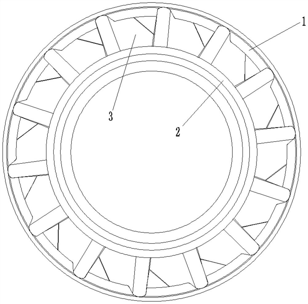
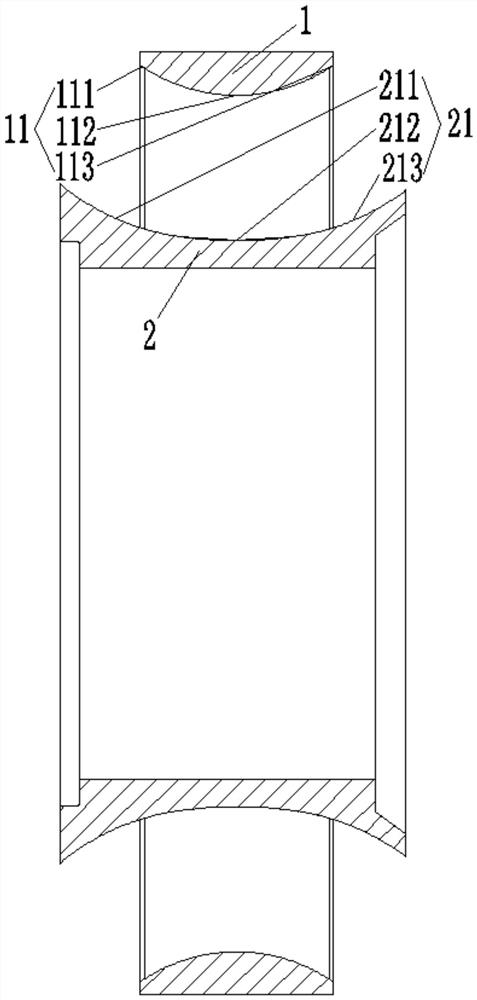
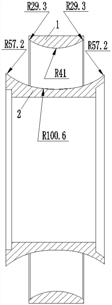
[0024] Such as Figure 1 to Figure 6 As shown, the construction machinery hydraulic torque converter guide wheel structure of this embodiment includes an outer ring 1 and an inner ring 2 arranged concentrically and a cascade 3 connected between the outer ring 1 and the inner ring 2, the outer ring 1 and the inner ring 2 A circular cavity is formed between the inner rings ...


PUM

PropertyMeasurementUnit
Thicknessaaaaaaaaaa
Thicknessaaaaaaaaaa

Abstract

The invention relates to a guide wheel structure of a hydraulic torque converter of engineering machinery. The guide wheel structure comprises an outer ring, an inner ring and a blade grid connected between the outer ring and the inner ring. A circulating circular cavity is formed between the outer ring and the inner ring, the blade grid comprises n blades which are uniformly arranged in the circumferential direction, n is greater than or equal to 12 and less than or equal to 16, n is an integer, a liquid flow channel with an inlet and an outlet is formed between every two adjacent blades, the inner ring arc face of the outer ring is composed of three arcs, the outer ring arc face of the inner ring is composed of three arcs, and the width of the guide wheel is effectively shortened; the inlet angle, the outlet angle and the streamline length of the guide wheel are designed, the guide wheel blades are of a spatial streamline structure, internal impact loss is reduced, the projection of the end faces of the outer ring ends of the blades falls into the end faces of the inner ring ends of the blades, die drawing is easy, and the manufacturability of the blades is improved; and the capacity of a hydraulic torque converter adopting the guide wheel structure is improved, and therefore the performance of the hydraulic torque converter is improved.

Description

technical field [0001] The invention relates to the technical field of engineering machinery hydraulic torque converters, in particular to a construction machinery hydraulic torque converter guide wheel structure. Background technique [0002] The hydraulic torque converter is a device that uses liquid as the working medium and uses the kinetic energy of the liquid for energy transmission. The pump wheel, turbine and guide wheel are the core components of the hydraulic torque converter. When the liquid flows through the guide wheel, because the guide wheel is fixed, the relative velocity of the liquid flow changes; changes in the velocity and direction of the liquid flow will lead to changes in the flow moment of the liquid, and the main function of the guide wheel is to change the momentum of the liquid moment. When the guide wheel changes the torque of the liquid flow, it also changes the form of the liquid flow and energy. Generally, the pressure energy of the liquid f...

Claims


Application Information

Patent Timeline
IPC IPC(8): F16H41/24F16H41/26
CPCF16H41/24F16H41/26
Inventor 李文跃杨国秀蔡祖戈
Owner JIANGSU ADVANCED CONSTR MASCH INNOVATION CENT LTD
Learn More