
Boiler waste heat utilization device

A technology of boiler waste heat and outer shell, applied in the direction of cleaning heat transfer devices, indirect heat exchangers, heat exchanger types, etc., can solve the problems of low utilization rate of boiler waste heat and shortening water heating time.

Pending Publication Date: 2021-09-10
涂小雨
View PDF0 Cites 0 Cited by
  • Summary
  • Abstract
  • Description
  • Claims
  • Application Information

AI Technical Summary

Problems solved by technology

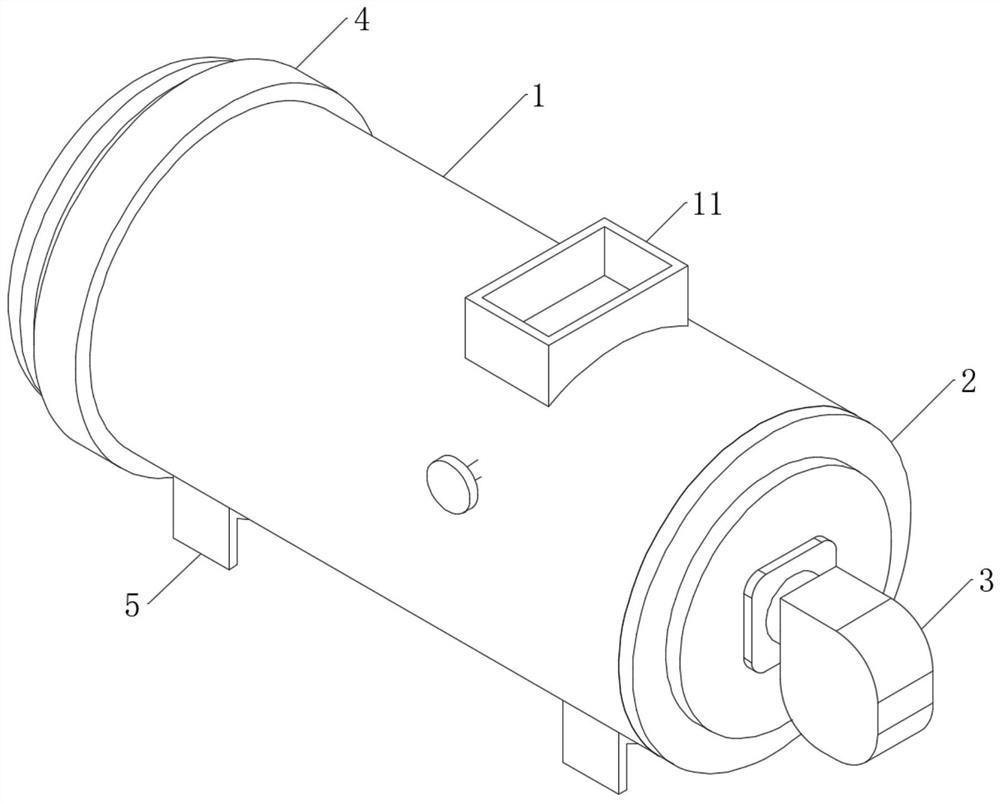
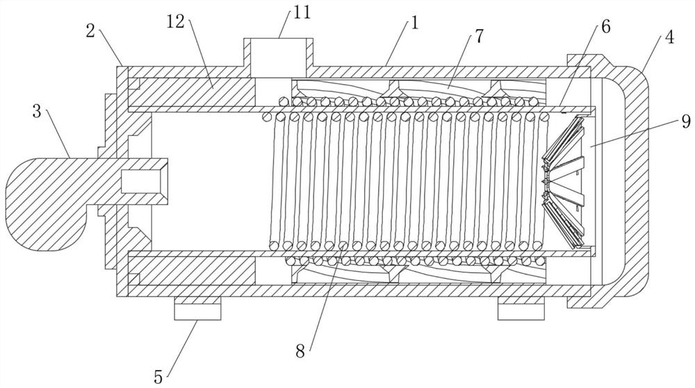
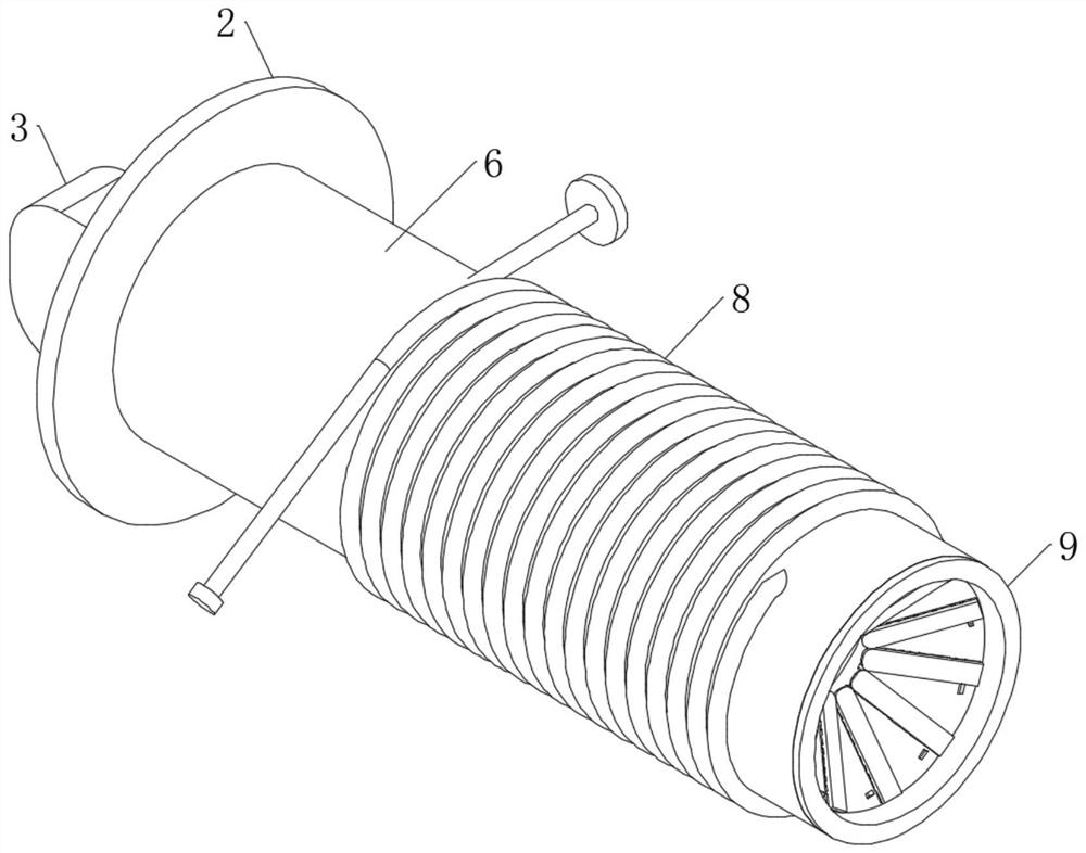
[0004] The purpose of the present invention is to provide a boiler waste heat utilization device. By wrapping part of the pipe body on the outside of the inner shell, part of the pipe body completes partial recovery of the heat absorbed by the inner shell, reducing heat loss and shortening the time for water heating. , to solve the problem of low utilization rate of existing boiler waste heat

Method used


Image

  • Boiler waste heat utilization device
  • Boiler waste heat utilization device
  • Boiler waste heat utilization device

Examples


Embodiment Construction

[0027] The following will clearly and completely describe the technical solutions in the embodiments of the present invention with reference to the accompanying drawings in the embodiments of the present invention. Obviously, the described embodiments are only some, not all, embodiments of the present invention. Based on the embodiments of the present invention, all other embodiments obtained by persons of ordinary skill in the art without creative efforts fall within the protection scope of the present invention.

[0028] In describing the present invention, it is to be understood that the terms "opening", "upper", "lower", "thickness", "top", "middle", "length", "inner", "surrounding" etc. Indicating orientation or positional relationship is only for the convenience of describing the present invention and simplifying the description, and does not indicate or imply that the components or elements referred to must have a specific orientation, be constructed and operated in a sp...


PUM


Abstract

The invention discloses a boiler waste heat utilization device, and relates to the technical field of waste heat utilization. The boiler waste heat utilization device comprises an outer shell and an inner shell, wherein the inner shell is coaxially installed in the outer shell, a smoke exhaust channel is formed between the outer shell and the inner shell, and a combustion chamber is formed in the inner shell; an end cover I and an end cover II are mounted at two opposite ports of the outer shell and the inner shell respectively in a sealing manner, and a combustor extending into the combustion chamber is mounted on the end cover I; and pipe bodies wind around the inner side and the outer side of the inner shell, the water inlet ends and the water outlet ends of the pipe bodies extend to the outside of the outer shell, and smoke exhaust holes are formed in the outer shell. Part of the pipe body winds around the outer side of the inner shell, part of the pipe body completes heat absorption of the inner shell to conduct partial recovery, heat loss is reduced, and meanwhile the water heating time is shortened.

Description

technical field [0001] The invention belongs to the technical field of waste heat utilization, in particular to a boiler waste heat utilization device. Background technique [0002] The work of energy saving and emission reduction is being promoted in an all-round way in the whole society, and a variety of energy saving and energy recovery methods have emerged accordingly. At present, my country's energy utilization rate is still at a low level, and waste heat recovery technology still has great development space and potential, so that a large amount of industrial waste heat / waste heat resources have not been effectively recycled due to the constraints of existing technologies. Taking the iron and steel industry as an example, the waste heat recovery rate of flue gas discharged from various furnaces in my country's iron and steel industry is only about 30%, which is far below the level of developed countries. Discharging all kinds of medium and high temperature flue gas dir...

Claims


Application Information

Patent Timeline
IPC IPC(8): F23J15/06F28D7/02F28G3/04F28G7/00F28G15/00F23J3/00
CPCF23J15/06F28D7/024F28G3/04F28G7/00F28G15/00F23J3/00Y02E20/30
Inventor 涂小雨
Owner 涂小雨
Learn More