
Furnace building system with compact kiln lining

A kiln lining and furnace building technology, applied in the direction of lining repair, etc., can solve the problems of decreased service life of furnace lining, weakened strength, poor uniformity of furnace building, etc.

Pending Publication Date: 2021-09-10
冷水江市润辰新材料有限公司
View PDF0 Cites 0 Cited by
  • Summary
  • Abstract
  • Description
  • Claims
  • Application Information

AI Technical Summary

Problems solved by technology

The furnace lining of manual furnace construction has good density and is not easy to damage the coils, etc., but the physical strength of the operators is high. At the same time, in order to improve the efficiency of manual furnace construction, multiple people are often used. The same, resulting in poor furnace uniformity
Pneumatic furnace building machine furnace can reduce the labor intensity of operators, but pneumatic furnace building is to vibrate the crucible wall by hammering the furnace wall horizontally, and then rely on the self-weight settlement of the furnace material to complete the furnace building. The density of the furnace material is compared with manual Poor, the thicker the furnace wall, the more obvious the situation; at the same time, because the force of the ramming material close to the coil is weakened, the working surface is loose. When the furnace body is used for a long period of time, it will Resulting in a rapid decline in the service life of the furnace lining

Method used


Image

  • Furnace building system with compact kiln lining
  • Furnace building system with compact kiln lining

Examples


Embodiment 1

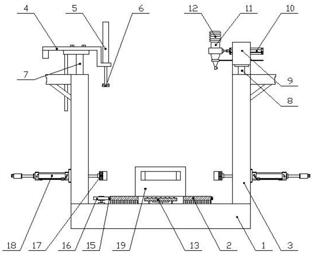
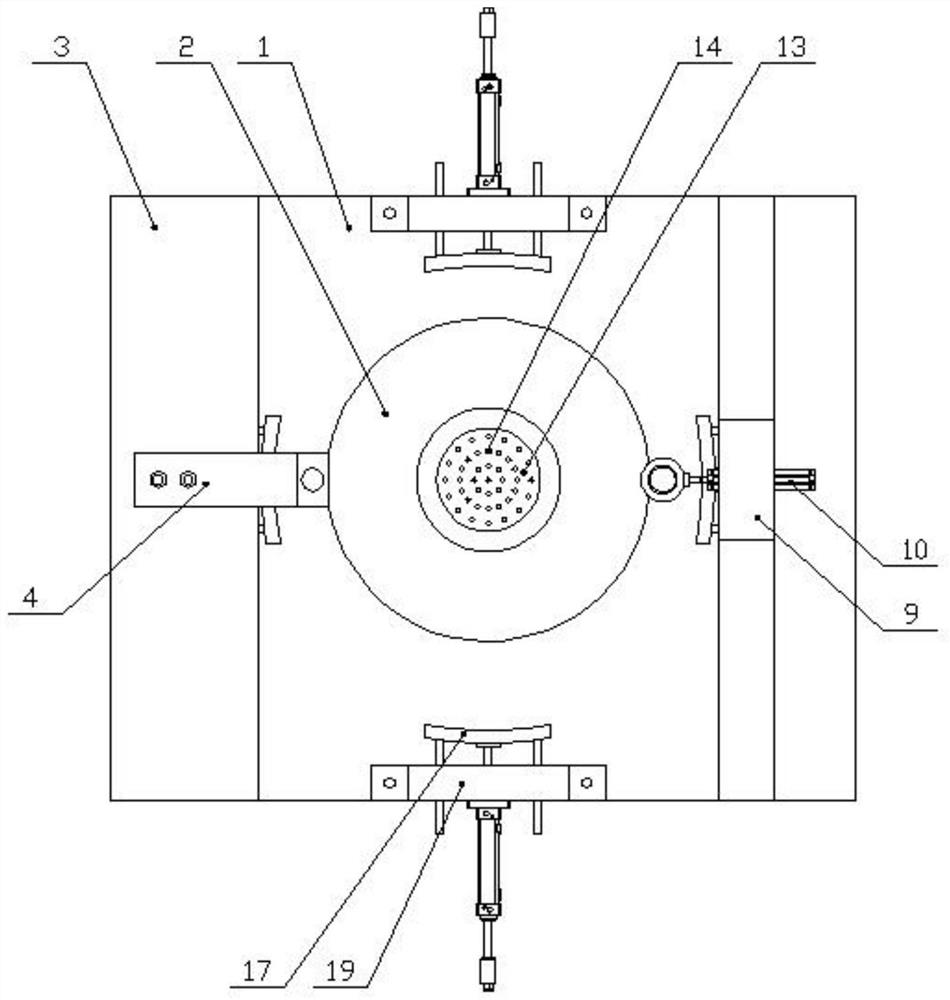
[0020] Example 1, such as Figure 1-Figure 2 As shown, the specific structure of this embodiment is as follows: it includes a base 1, a feeding mechanism, and a tamping mechanism. The middle part of the upper end of the base 1 is provided with a bearing plate 2 with a horizontal upper end surface, and the bearing plate 2 rotates around its vertical axis. The upper end of the base 1 is provided with a support frame 3 on the outside of the carrier plate 2. In this embodiment, there are two support frames 3 at intervals on the left and right. The gap between the support frames 3 is convenient for hoisting the kiln to the carrier plate 2; Described building tamping mechanism comprises installation frame 4, ramming driving device 5, ramming part 6, and described installation frame 4 is arranged on support frame 3 top, and vertical drive part 7 is vertically arranged in one side support frame 3, vertically The driving part 7 can adopt an oil cylinder, etc., and the piston rod of the...

Embodiment 2

[0022] Example 2, such as Figure 1-2 As shown, other structures of the present embodiment are the same as those of Embodiment 1, but in the present embodiment, a feeding vertical pusher 8 is provided on the other side support frame 3 opposite to the tamping mechanism, and the feeding vertical pusher 8 can be Adopt oil cylinder etc., described feeding vertical pushing part 8 is connected with lifting part 9 in feeding mechanism, and lifting part 9 is arranged in the storage groove of support frame 3, and described lifting part 9 is provided with feeding horizontal pushing part 10, and feeding The horizontal pushing part 10 can adopt an electric push rod, a cylinder, etc., and the feeding horizontal pushing part 10 is connected with the lower hopper 11 in the feeding mechanism. 12 can use hoses, telescopic tubes, etc.; the mounting bracket 4 and the bottom plate are connected by bolts, and threaded holes are arranged on the bottom plate at radial intervals along the bearing pla...

Embodiment 3

[0024] Example 3, such as Figure 1-2 As shown, the other structures of this embodiment are the same as those of Embodiment 1, but in this embodiment, the carrying plate 2 is ring-shaped, and the middle part of the carrying plate 2 is provided with a jacking portion 13 that moves in the vertical direction, and the base 1 An oil cylinder for driving the lifting part 13 is arranged inside, and the upper end of the lifting part 13 is provided with a universal wheel 14; the outer side of the carrying plate 2 is provided with a centering plate 17 moving in the horizontal direction in a circular array of its axes, The centering plate 17 is arc-shaped, and its center of circle is located on one side of the carrier plate 2. In this embodiment, there are four centering plates 17, and the angle between any two of them is 90 degrees. The centering plate 17 and the Horizontal promotion oil cylinder 18 is connected, and the horizontal promotion oil cylinder 18 that is arranged on one side ...


PUM


Abstract

The invention discloses a furnace building system with a compact kiln lining, which belongs to the field of furnace building, comprises a base, a feeding mechanism and a building and ramming mechanism, and is characterized in that a bearing disc with a horizontal upper end surface is arranged in the middle of the upper end of the base, the bearing disc rotates around the vertical axis of the bearing disc, and a support frame is arranged on the outer side of the bearing disc at the upper end of the base; the building and ramming mechanism comprises a mounting frame, a ramming driving device and a ramming part, the supporting frame is provided with a vertical driving part used for driving the mounting frame to move in the vertical direction; the ramming driving device is arranged on the side, facing the bearing disc, of the mounting frame, and the ramming part is mounted at the lower end of the ramming driving device; and a feeding mechanism is further arranged on the supporting frame. The invention aims to provide the furnace building system with the compact kiln lining, and materials wound on a chain scraper conveyor can be quickly and thoroughly removed.

Description

technical field [0001] The invention relates to the field of furnace building, in particular to a furnace building system with a dense inner lining of a furnace. Background technique [0002] Furnaces such as intermediate frequency furnaces are commonly used in two ways: manual furnace construction and pneumatic furnace construction machine furnace construction. The furnace lining of manual furnace construction has good density and is not easy to damage the coils, etc., but the physical strength of the operators is high. At the same time, in order to improve the efficiency of manual furnace construction, multiple people are often used. The same, resulting in poor furnace uniformity. Pneumatic furnace building machine furnace can reduce the labor intensity of operators, but pneumatic furnace building is to vibrate the crucible wall by hammering the furnace wall horizontally, and then rely on the self-weight settlement of the furnace material to complete the furnace building....

Claims


Application Information

Patent Timeline
Patent Type & Authority Applications(China)
IPC IPC(8): F27D1/16
CPCF27D1/16
Inventor 刘澄
Owner 冷水江市润辰新材料有限公司
Learn More