
Solid heat storage device with high-stability heat storage and high-efficiency heat release

A high stability, heat storage device technology, applied in heat storage equipment, heat exchanger types, indirect heat exchangers, etc., can solve the problem of lack of thermal stress release components, low thermal energy utilization rate, and large resistance of steam heat release circulation channels. And other issues

Pending Publication Date: 2021-09-10
SHENYANG SHIJIE ELECTRIC
View PDF1 Cites 2 Cited by
  • Summary
  • Abstract
  • Description
  • Claims
  • Application Information

AI Technical Summary

Problems solved by technology

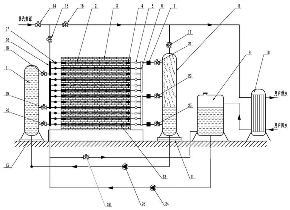
[0002] The company is using the technology in "A heat storage and heat conversion device built with solid blocks" (see patent: 202020175002.5) to provide solid steam heat storage and heat release devices for coal-fired and gas-fired thermal power plants and heat source plants , when storing excess steam heat energy for users, it is found that the existing technology has the following deficiencies: 1. There are too many valves; 3. When the device is in the exothermic working state, since the solid heat storage body is not partitioned according to different heat storage temperatures, the thermal energy utilization rate is low in the solid heat storage body partition with a lower heat storage temperature; 4. Embedded in solid The heat exchange tube in the heat storage body is not equipped with a thermal expansion buffer structure, so that the metal heat exchange tube with a larger thermal linear expansion coefficient will expand and crack the solid heat storage body with a lower linear expansion coefficient; 5. There is no thermal stress between the various parts of the device release component

Method used


Image

  • Solid heat storage device with high-stability heat storage and high-efficiency heat release

Examples


example 1

[0015] As shown in Figure 1, water supply tank 1, solid heat storage body 3, heat exchange tube 12, flexible head 4, output horizontal main pipe 5, output longitudinal main pipe 6, input vertical main pipe 26, and input horizontal main pipe 27 , a saturated steam tank 8, a water storage tank 9, a heat exchanger 10, a fixed support 13 is provided at the lower part of the water supply tank 1, and a sliding support 11 is provided at the lower part of the saturated steam tank 8; The heat transfer pipe between the output longitudinal main pipe 6 and the saturated steam tank body 8 is evenly distributed with expansion joints 7 for buffering the axial thrust of the heat exchange tube group on the saturated steam tank body 8; the steam heat source passes through the pipeline, the main valve 14 And the heat storage valve 15 is connected with the input longitudinal main pipe 26 connected with the high-level circulating water valve 18 and the multiple input horizontal main pipes 27 connec...


PUM


Abstract

The invention discloses a solid heat storage device with high-stability heat storage and high-efficiency heat release. The device comprises a steam heat source, a solid heat storage body, a water supply tank body, a saturated steam tank body, a water storage tank, a heat exchanger and a valve. The device is technically characterized in that a fixed support is arranged at the lower part of the water supply tank body, and a sliding support is arranged at the lower part of the saturated steam tank body; expansion joints for buffering the axial thrust of heat exchange tube sets on the saturated steam tank body are uniformly distributed on a heat transfer tube between an output longitudinal mother tube of the solid heat storage body and the saturated steam tank body; the steam heat source is sequentially connected with the heat exchange tube set arranged at the top end of the solid heat storage body through pipelines and steam valves, and communicated with the adjacent heat exchange tube set on the lower layer in series through the longitudinal mother tubes to form a snakelike reciprocating connection structure. and the sliding support on the lower portion of the saturated steam tank body moves so as to eliminate thrust generated on the saturated steam tank body after buffering of the expansion joints.

Description

technical field [0001] The invention belongs to the technical field of solid heat storage, and in particular relates to a solid heat storage device with high-stability heat storage and high-efficiency heat release. Background technique [0002] The company is using the technology in "A heat storage and heat conversion device built with solid blocks" (see patent: 202020175002.5) to provide solid steam heat storage and heat release devices for coal-fired and gas-fired thermal power plants and heat source plants , when storing excess steam heat energy for users, it is found that the existing technology has the following deficiencies: 1. There are too many valves; 3. When the device is in the exothermic working state, since the solid heat storage body is not partitioned according to different heat storage temperatures, the thermal energy utilization rate is low in the solid heat storage body partition with a lower heat storage temperature; 4. Embedded in solid The heat exchange...

Claims


Application Information

Patent Timeline
IPC IPC(8): F28D20/00
CPCF28D20/0056Y02E60/14
Inventor 朱建新
Owner SHENYANG SHIJIE ELECTRIC
Learn More