
Testing fixture based on carbon fiber frameworks, and manufacturing method thereof

A carbon fiber and skeleton technology, applied in the field of inspection fixtures, can solve problems such as heavy weight, insufficient connection strength between pipes, ugly and bulky inspection fixtures, etc.

Pending Publication Date: 2021-09-10
ROYAL GAUGE IND
View PDF0 Cites 0 Cited by
  • Summary
  • Abstract
  • Description
  • Claims
  • Application Information

AI Technical Summary

Problems solved by technology

The first is to use foam as a model with a rectangular cross-section, use carbon fiber boards to stick on the foam, glue the intersections to form a skeleton, then glue the bakelite board to the skeleton, and process the surface of the bakelite board as The installation surface is installed with other detection block parts. Since many intersections of this kind of skeleton are connected by glue, the corners will crack after the inspection tool is used for more than half a year, and the inspection tool is ugly and heavy, and it is not easy to process and measure. It is convenient for clamping and fixing; the second is to fix the carbon fiber pipes with glue, and then glue the installation block on the pipe, and install other detection block parts by processing the surface of the installation block as the installation surface. The connection strength between the pipes of the skeleton is not good enough, all the detection blocks are locked, which is relatively heavy, and it is not convenient to clamp and fix during processing and measurement

Method used


Image

  • Testing fixture based on carbon fiber frameworks, and manufacturing method thereof
  • Testing fixture based on carbon fiber frameworks, and manufacturing method thereof
  • Testing fixture based on carbon fiber frameworks, and manufacturing method thereof

Examples


Embodiment Construction

[0044] The following will clearly and completely describe the technical solutions in the embodiments of the present invention with reference to the accompanying drawings in the embodiments of the present invention. Obviously, the described embodiments are only some, not all, embodiments of the present invention. Based on the embodiments of the present invention, all other embodiments obtained by persons of ordinary skill in the art without making creative efforts belong to the protection scope of the present invention.

[0045] In the description of the present invention, it should be noted that the orientation or positional relationship indicated by the terms "upper", "lower", "bottom", "inner" and "outer" are based on the orientation or positional relationship shown in the drawings , is only for the convenience of describing the present invention and simplifying the description, but does not indicate or imply that the referred device or element must have a specific orientatio...


PUM


Abstract

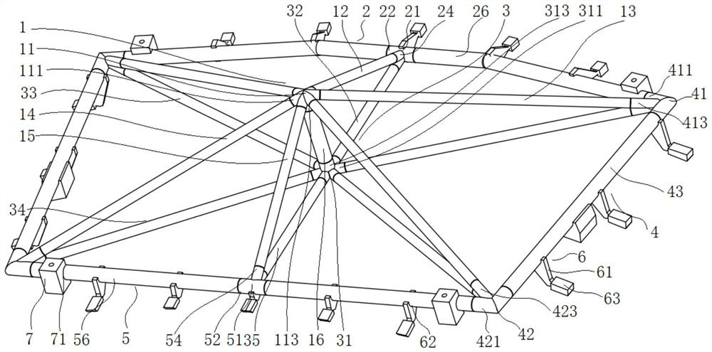
The invention discloses a testing fixture based on carbon fiber frameworks. The testing fixture comprises a plurality of first joints, a plurality of second joints, a plurality of third joints, a plurality of fourth joints, a plurality of fifth joints, a plurality of sixth joints, a plurality of first frameworks, a plurality of second frameworks, a plurality of third frameworks, a plurality of fourth frameworks and a plurality of fifth frameworks. A manufacturing method of the testing fixture based on carbon fiber frameworks comprises the following steps: manufacturing the first joints, the second joints, the third joints, the fourth joints, the fifth joints and the sixth joints; manufacturing the frameworks; manufacturing a detection block; and manufacturing a reference block. The weight is effectively reduced, machining and measuring are convenient, errors are small, and precision is guaranteed.

Description

technical field [0001] The invention relates to the field of inspection fixture manufacturing, in particular to a carbon fiber skeleton-based inspection fixture and a manufacturing method. Background technique [0002] There are mainly two types of carbon fiber frame inspection tools in the past. The first is to use foam as a model with a rectangular cross-section, use carbon fiber boards to stick on the foam, glue the intersections to form a skeleton, then glue the bakelite board to the skeleton, and process the surface of the bakelite board as The installation surface is installed with other detection block parts. Since many intersections of this kind of skeleton are connected by glue, the corners will crack after the inspection tool is used for more than half a year, and the inspection tool is ugly and heavy, and it is not easy to process and measure. It is convenient for clamping and fixing; the second is to fix the carbon fiber pipes by jointing each other with glue, a...

Claims


Application Information

Patent Timeline
IPC IPC(8): G01D21/00B29C69/00
CPCG01D21/00B29C69/00
Inventor 王永定谭利军董力
Owner ROYAL GAUGE IND
Learn More