
Super-resolution vertical detection method for ionosphere Es layer

A super-resolution and vertical detection technology, which is applied in the field of ionospheric detection, can solve the problems that have not been proposed for super-resolution sweeping observations of vertical surveyors, without considering the smoothing method of frequency dimension, and it is difficult to obtain the fine structure of Es thin layer, evolution process and Volatility and other issues

Active Publication Date: 2021-09-10
WUHAN UNIV
View PDF8 Cites 4 Cited by
  • Summary
  • Abstract
  • Description
  • Claims
  • Application Information

AI Technical Summary

Problems solved by technology

[0004] As a conventional observation method, the ionospheric dipmeter can directly and continuously obtain various macroscopic information of Es, and the occurrence and cut-off frequency, occurrence height, type, and shadowing situation of Es are given on the frequency-high map. However, limited by the observation distance resolution of only kilometers, it is difficult to obtain the fine structure, evolution process and fluctuation characteristics in the vertical direction in the Es thin layer
[0005] In addition, in the current technology, although some researchers have used multi-frequency coherent technology to achieve high-resolution observations of ionospheric or tropospheric turbulence in VHF radars, the results often only reflect the response of the target to a certain center frequency There is no clear design scheme for the setting of detection parameters, and no related method is proposed to realize the super-resolution frequency sweep observation of the Es layer by using the vertical survey instrument, and the frequency dimension smoothing method for the frequency sweep observation results is not considered.

Method used

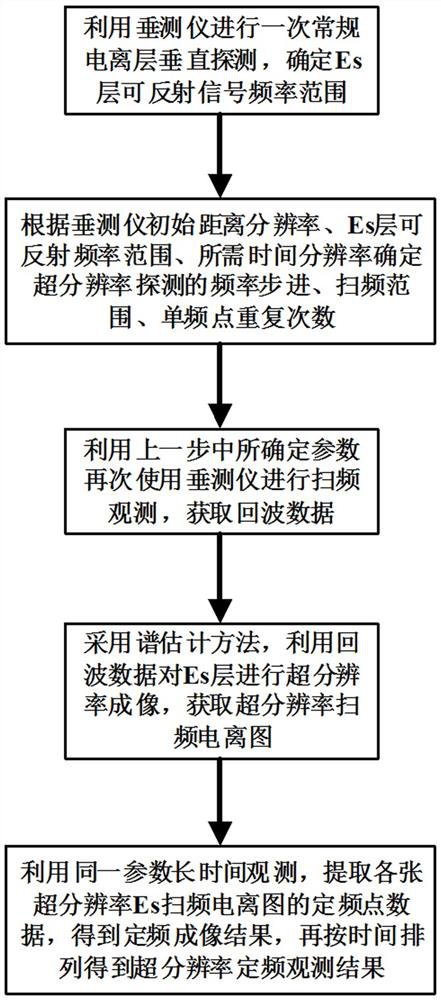
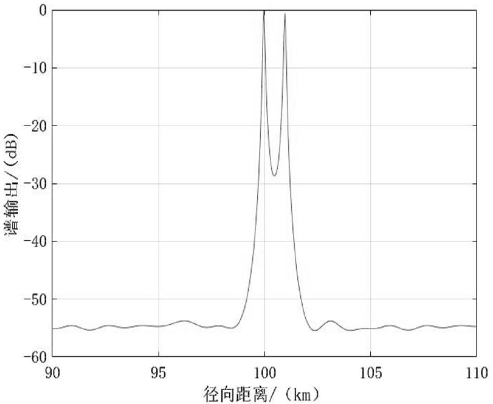

Image

  • Super-resolution vertical detection method for ionosphere Es layer
  • Super-resolution vertical detection method for ionosphere Es layer
  • Super-resolution vertical detection method for ionosphere Es layer

Examples


Embodiment Construction

[0055] Embodiments of the present invention will be described in detail below in conjunction with the accompanying drawings.

[0056] This embodiment provides a super-resolution vertical detection method of the ionosphere Es layer, using conventional vertical survey equipment, the distance resolution of the vertical observation of the ionosphere Es layer can be greatly improved without increasing additional hardware costs, It is beneficial to study the fine structure, evolution process and fluctuation characteristics of the Es layer in the vertical direction.

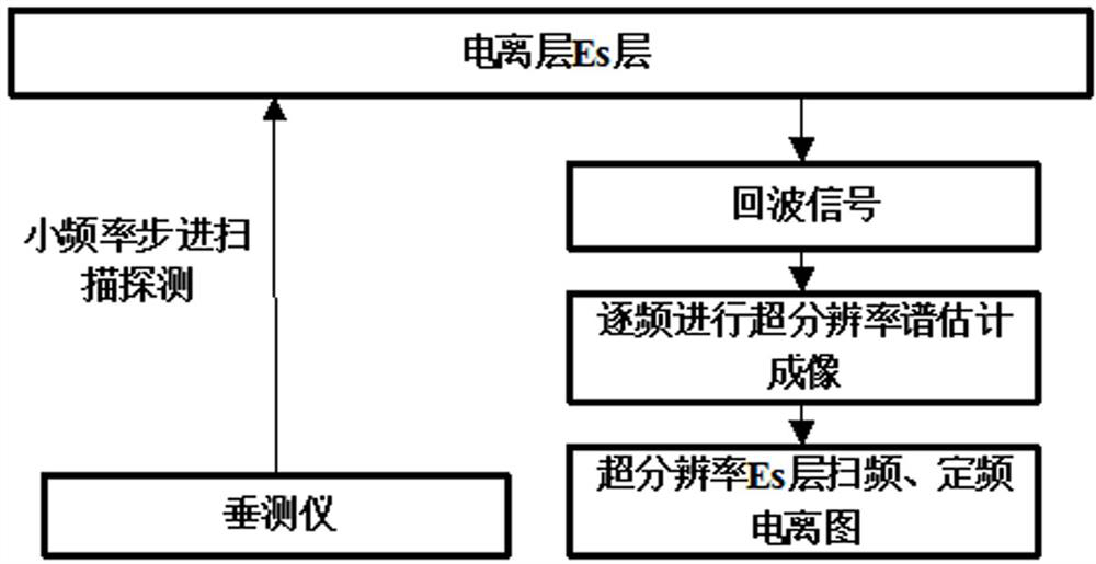
[0057] The basic principle of this embodiment is as figure 1 As shown, the short-wave signal is transmitted to the Es layer in the vertical direction in the form of small frequency steps for frequency scanning detection, and then the coherence between the similar-frequency short-wave signals reflected by the same Es layer area is used to carry out the step-by-step spectral estimation method. The frequency super-resolu...


PUM


Abstract

The invention discloses a super-resolution vertical detection method for an ionosphere Es layer, which comprises the following steps: transmitting a short wave signal to the Es layer in the vertical direction by using a vertical measuring instrument in a small-frequency stepping form to carry out frequency sweeping detection,wherein the frequency stepping ensures that imaging blur is not generated through accurate design; and then, carrying out frequency-by-frequency super-resolution distance imaging by adopting a spectrum estimation method by utilizing coherence between short-wave signals with similar frequencies reflected by the same Es layer region, so as to achieve Es layer super-resolution observation and naturally finish frequency dimension smoothing. Compared with the prior art, the method has the advantages that the range resolution of Es layer observation can be greatly improved by only adopting a conventional vertical measuring instrument system without additional equipment and hardware cost, a super-resolution Es layer sweep frequency ionogram can be obtained, and a super-resolution fixed frequency observation result can also be obtained; according to the method, the fine structure, the evolution process and the fluctuation characteristics of the Es layer in the vertical direction can be observed only by using the vertical measuring instrument.

Description

technical field [0001] The invention belongs to the technical field of ionospheric detection, in particular to a super-resolution vertical detection method of the Es layer of the ionosphere. Background technique [0002] The ionospheric Es layer is an inhomogeneous structure in the E layer. Its individual characteristics are sporadic, and the formation and maintenance time is not easy to predict. It can exist for tens of minutes to several hours, so it is often called "sporadic E layer. "(sporadic-E). In terms of morphology and structure, the Es layer is in the form of a "thin layer" in the vertical direction, distributed at a height of 90-130km, the electron density is higher than that of the background E layer and there is a large gradient, which can form a shield or semi-shade for the F layer. Although it is usually only 0.2-5km, there may also be stratification inside; and in the horizontal direction, its structure is also more diverse, which can be in the form of "plat...

Claims


Application Information

Patent Timeline
IPC IPC(8): G01S13/89
CPCG01S13/89
Inventor 刘桐辛杨国斌姜春华周晨赵正予
Owner WUHAN UNIV
Learn More