An optical fiber link detection system and method based on digital modulation signal

A digital linear and frequency modulation signal technology, applied in the transmission system, electromagnetic wave transmission system, electrical components, etc., can solve the problems of high cost, conflict between dynamic range and measurement resolution, and achieve the effect of increasing equipment cost

Inactive Publication Date: 2018-12-18
WUHAN POST & TELECOMM RES INST CO LTD
View PDF5 Cites 0 Cited by
  • Summary
  • Abstract
  • Description
  • Claims
  • Application Information

AI Technical Summary

Problems solved by technology

[0006] The technical problem to be solved by the present invention is that the existing optical time domain reflectometer has a high cost and cannot solve the conflicting problem of dynamic range and measurement resolution

Method used


Image

  • An optical fiber link detection system and method based on digital modulation signal
  • An optical fiber link detection system and method based on digital modulation signal
  • An optical fiber link detection system and method based on digital modulation signal

Examples


specific Embodiment 1

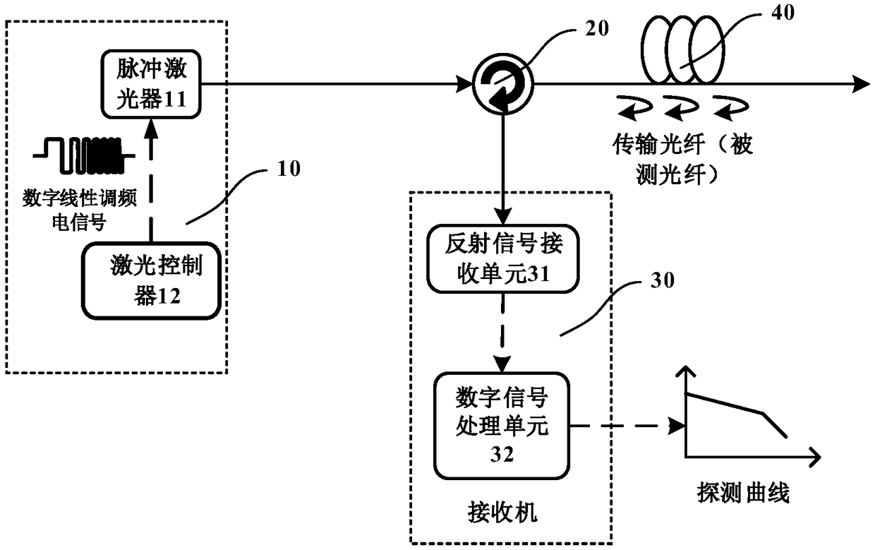
[0050] Such as figure 1 As shown, the digital chirp signal-based optical fiber link detection system provided in Embodiment 1 of the present invention includes a digital chirp signal generator 10 , a circulator 20 and a receiver 30 .

[0051] The digital chirp signal generator 10 is used to generate a digital chirp signal as a detection signal, and convert it into an optical pulse and inject it into the optical fiber 40 to be detected. In this specific embodiment, the digital chirp signal generator 10 is composed of a pulsed laser 11 and a laser controller 12 . The pulsed laser 11 is used to generate a pulsed optical signal. The laser controller 12 uses the periodic digital chirp electrical signal generated by the FPGA to control the pulsed laser 11 through the driver to generate corresponding optical pulses, and is injected into the detected optical fiber 40 by the circulator 20. (transmission fiber).

[0052] On the one hand, the circulator 20 injects light pulses into the...

specific Embodiment 2

[0064] In Embodiment 2 of the present invention, the receiver 30 includes a reflected signal receiving unit 31 and a digital signal processing unit 32 . The reflection signal receiving unit 31 is used to receive the backscatter signal output from the circulator 20 , convert it into a digital signal and transmit it to the digital signal processing unit 32 . The digital signal processing unit 32 is used to receive the digital signal output by the reflected signal receiving unit 31, and extract the optical fiber characteristics of the detected optical fiber carried on the chirp signal from the digital signal.

[0065] Further, the digital signal processing unit 32 uses the fractional Fourier transform algorithm to separate the chirp signals of different frequency modulation ranges from the noise, respectively extract the chirp signals of different frequency modulation ranges, and superimpose them, and output the curve track of the detection signal As an output result, the charact...

specific Embodiment 3

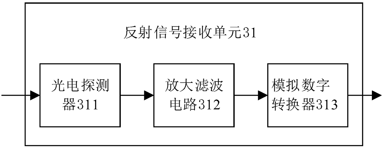
[0068] Such as image 3 As shown, the reflected signal receiving unit 31 includes a photodetector 311, an amplification and filtering circuit 312, and an analog-to-digital converter 313. The photodetector 311 is used to convert the backscattered signal from the circulator 20 into an analog electrical signal, and the amplification and filtering circuit 312 is used to amplify the analog electrical signal output by the photodetector 311 to filter part of the noise, and the analog-to-digital converter 313 is used to convert the analog electrical signal into a digital electrical signal for subsequent digital signal processing. Therefore, the conversion of the photoelectric signal to the digital signal is realized, and a part of the noise is filtered out, thereby improving the signal quality.


PUM


Abstract

The invention discloses an optical fiber link detection system and a method based on a digital linear frequency modulation signal. The system comprises a digital modulation signal generator, a circulator and a receiver. The digital modulation signal generator is used for generating a detection signal in the form of a digital modulation optical pulse and injecting the detected optical fiber throughthe circulator. The receiver extracts the detected optical fiber features carried by the detection signal from the backscattered signal. The invention utilizes the characteristic that the linear frequency modulation signal has excellent energy gathering in the fractional Fourier domain, by using digital LFM optical pulse as detection signal, LFM signals with different FM ranges are separated fromnoise in backscattered signals, and the characteristics of detected optical fiber are extracted, which can improve the dynamic range and measurement range resolution of optical fiber link detection simultaneously without increasing the cost.

Description

technical field [0001] The invention relates to the technical field of optical fiber communication, in particular to an optical fiber link detection system and method based on digital chirp signals. Background technique [0002] An Optical Time Domain Reflectometer (OTDR) is an instrument commonly used in the telecommunications field to measure the characteristics of optical fibers. It can measure optical fiber characteristics such as transmission loss, connector attenuation, fiber length, and interruption points. Its working principle is: inject a series of optical pulse signals into the detected optical fiber as the detection signal, and receive the reflected backscattering signal on the same side of the injected optical pulse, because the optical pulse signal injected into the detected optical fiber encounters different Rayleigh scattering (Rayleigh scattering) will occur when the medium has a refractive index and will be reflected back by the fiber under test, so the cha...

Claims


Application Information

Patent Timeline
IPC IPC(8): H04B10/071
Inventor 李蔚余少华张谱
Owner WUHAN POST & TELECOMM RES INST CO LTD
Why Eureka
Try Eureka