Efficient heat dissipation electric appliance cabinet for electrical engineering
A technology for electrical engineering and electrical cabinets, applied in electrical components, substation/distribution device enclosures, substation/switch layout details, etc., which can solve problems such as poor heat dissipation effect and low heat dissipation efficiency
- Summary
- Abstract
- Description
- Claims
- Application Information
AI Technical Summary
Problems solved by technology
Method used
Image

Examples
Embodiment 1
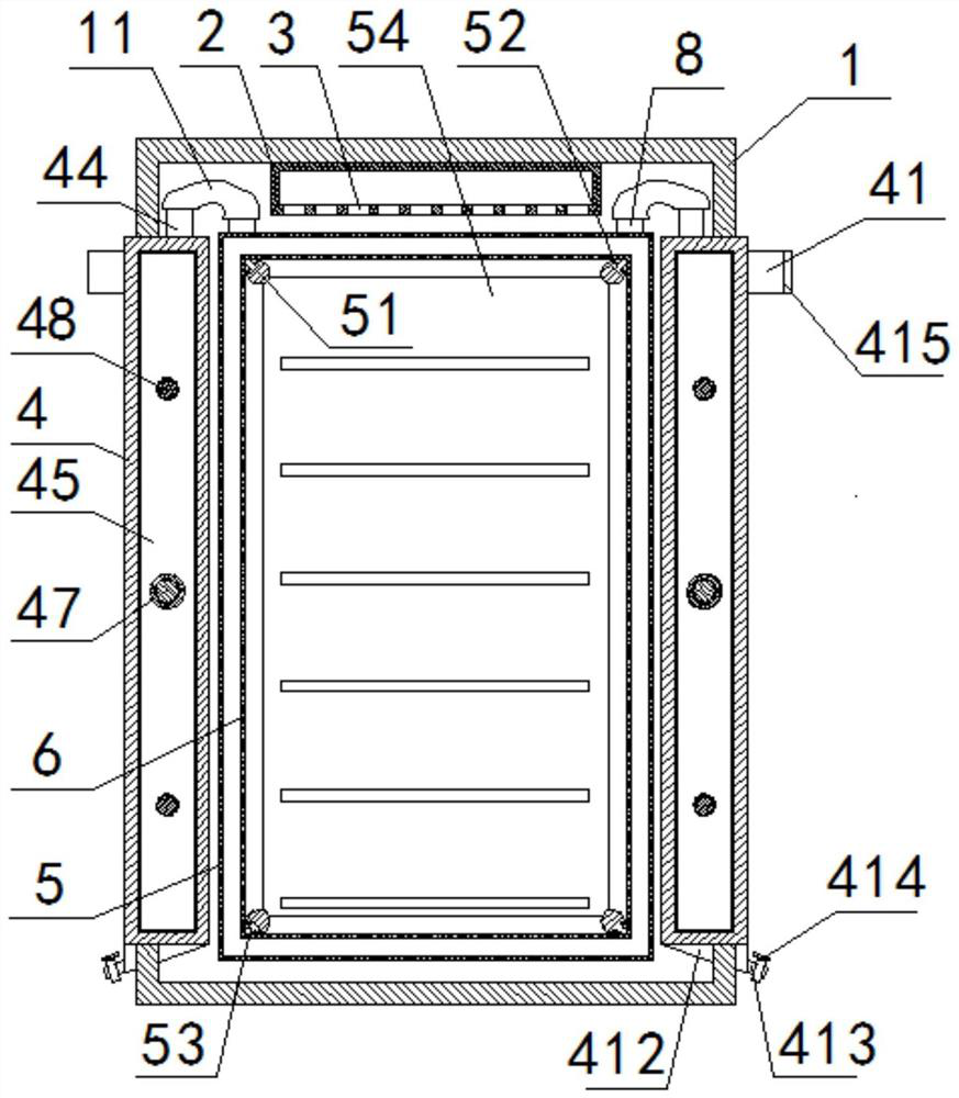
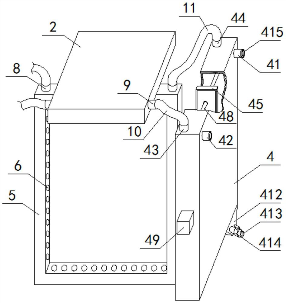
[0054] see Figure 1 to Figure 9 , a high-efficiency heat dissipation electrical cabinet for electrical engineering, comprising a cabinet body 1, a cabinet body 2 is arranged on the inner top wall of the cabinet body 1, and a plurality of ventilation holes 3 are uniformly arranged on the bottom of the cabinet body 2, and the Gas exchange components 4 are inserted on the inner walls of both sides of the cabinet body 1, and a square tube 5 is arranged inside the cabinet body 1, and the square tube 5 is located between two gas exchange components 4. The two ends of the top of the exchange assembly 4 communicate with the side of the box body 2 and the top of the square tube 5 respectively, and a plurality of cooling holes 6 are evenly opened on the inside of the square tube 5; the outer wall of the gas exchange assembly 4 is provided with The intake pipe 41 and the exhaust pipe 42 are arranged at both ends of the side of the gas exchange assembly 4 away from the square pipe 5 .
...
Embodiment 2
[0059] Basic content is the same as embodiment 1, the difference is:
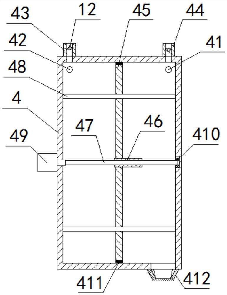
[0060] see Figure 1 to Figure 9 , the interior of the cabinet 1 is provided with an electric telescopic rod 7, one end of the electric telescopic rod 7 is connected to one side inner wall of the cabinet body 1, and the other end of the electric telescopic rod 7 is connected to the outer side wall of the square tube 5 back. connection; the outer wall of the gas exchange assembly 4 is provided with a first connecting pipe 43 and a second connecting pipe 44, and the inlet pipe 41, the exhaust pipe 42, the first connecting pipe 43 and the second connecting pipe 44 are all provided There is a one-way valve 12, the first connecting pipe 43 and the second connecting pipe 44 are respectively arranged at both ends of the top of the gas exchange assembly 4, and the gas exchange assembly 4 communicates with the box body 2 through the first connecting pipe 43, and the gas The exchange assembly 4 communicates with the...
Embodiment 3
[0062] Basic content is the same as embodiment 1, the difference is:
[0063] see Figure 1 to Figure 9 , four fixed rods 51 are arranged between the inner walls of the front and rear sides of the cabinet body 1, the fixed rods 51 are located at the four corners inside the square tube 5, and T-shaped grooves 52 are arranged on the outer surface of the fixed rods 51 A T-shaped slider 53 is slidably connected in the T-shaped groove 52, and the T-shaped slider 53 is fixedly connected with the square tube 5, and an electrical component mounting plate 54 is arranged between the four fixed rods 51. A filter 415 is disposed inside the intake pipe 41 .
PUM
 Abstract
Description
Claims
Application Information
 - R&D
- Intellectual Property
- Life Sciences
- Materials
- Tech Scout
- Unparalleled Data Quality
- Higher Quality Content
- 60% Fewer Hallucinations
Browse by: Latest US Patents, China's latest patents, Technical Efficacy Thesaurus, Application Domain, Technology Topic, Popular Technical Reports.
© 2025 PatSnap. All rights reserved.Legal|Privacy policy|Modern Slavery Act Transparency Statement|Sitemap|About US| Contact US: help@patsnap.com