Supercharge Your Innovation With Domain-Expert AI Agents!

Chip heat dissipation system

A chip heat dissipation and chip technology, which is applied in the direction of cooling/ventilation/heating transformation, electrical components, electrical equipment structural parts, etc., can solve the problems of system temperature rise, limited physical size of the heat sink, blocking the air duct of the heat sink, etc.

Pending Publication Date: 2021-09-10
S2C
View PDF8 Cites 0 Cited by
  • Summary
  • Abstract
  • Description
  • Claims
  • Application Information

AI Technical Summary

Problems solved by technology

However, in the existing system, the FPGA and a large number of connectors are placed on the same side of the system, so the physical size of the heat sink will be limited; in addition, the outgoing lines of a large number of connectors on the same side will physically interfere with the heat sink, and even block heat dissipation Air duct of the device
Heat accumulated inside the system for a long time will cause the temperature of the system to rise, thus affecting the performance and reliability of the system

Method used


Image

  • Chip heat dissipation system
  • Chip heat dissipation system

Examples


Embodiment Construction

[0019] Embodiments of the present disclosure will be described in detail below in conjunction with the accompanying drawings.

[0020] Embodiments of the present disclosure are described below through specific examples, and those skilled in the art can easily understand other advantages and effects of the present disclosure from the contents disclosed in this specification. Apparently, the described embodiments are only some of the embodiments of the present disclosure, not all of them. The present disclosure can also be implemented or applied through different specific implementation modes, and various modifications or changes can be made to the details in this specification based on different viewpoints and applications without departing from the spirit of the present disclosure. It should be noted that, in the case of no conflict, the following embodiments and features in the embodiments can be combined with each other. Based on the embodiments in the present disclosure, a...


PUM


Abstract

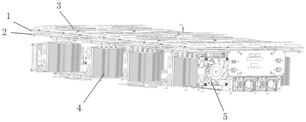
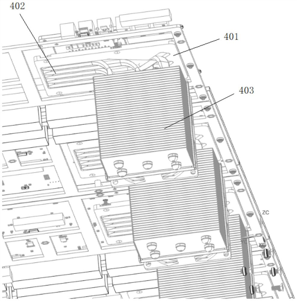
The embodiment of the invention provides a chip heat dissipation system, which comprises a carrier plate, a chip, a system connector and a heat dissipation device, wherein the chip and the system connector are arranged on the carrier plate, the heat dissipation device is arranged on the chip, and the system connector and the chip are arranged on the two sides of the carrier plate respectively. According to the invention, the chip heat dissipation system can quickly discharge heat from the system, so that the temperature of the FPGA and the whole system can be quickly reduced, wiring or card insertion on the connector on the front side of the system becomes easy without physical interference, and networking of the whole system is facilitated.

Description

technical field [0001] The present disclosure relates to the technical field of integrated circuits, in particular to a chip cooling system. Background technique [0002] The existing chip prototype verification system or hardware emulator uses a large-capacity and high-performance FPGA, and the maximum dynamic power consumption of the FPGA can reach 200W, so an efficient heat dissipation device is essential. The current general practice is to install a cooling device above the FPGA. The cooling device conducts heat to the cooling fins through close contact with the FPGA, and then discharges the heat from the cooling fins through the fan, thereby reducing the temperature of the FPGA. However, in the existing system, the FPGA and a large number of connectors are placed on the same side of the system, so the physical size of the heat sink will be limited; in addition, the outgoing lines of a large number of connectors on the same side will physically interfere with the heat si...

Claims


Application Information

Patent Timeline
IPC IPC(8): H05K7/20
CPCH05K7/20145H05K7/20409Y02D10/00
Inventor 曹叶
Owner S2C
Features
  • R&D
  • Intellectual Property
  • Life Sciences
  • Materials
  • Tech Scout
  • Unparalleled Data Quality
  • Higher Quality Content
  • 60% Fewer Hallucinations
Learn More