Tower crane emergency escape self-rescue knapsack type slow down device and its use method
A knapsack-style, emergency technology, applied in the field of escape knapsack slow down, can solve the problems that affect the user's life safety, poor safety and protection performance, unable to automatically and manually lock, etc., to achieve convenient and quick adjustment, improve safety and Reliability and good effect
- Summary
- Abstract
- Description
- Claims
- Application Information
AI Technical Summary
Problems solved by technology
Method used
Image
Examples
Embodiment 1
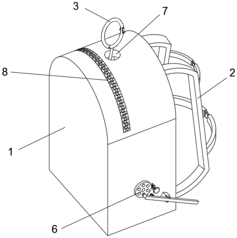
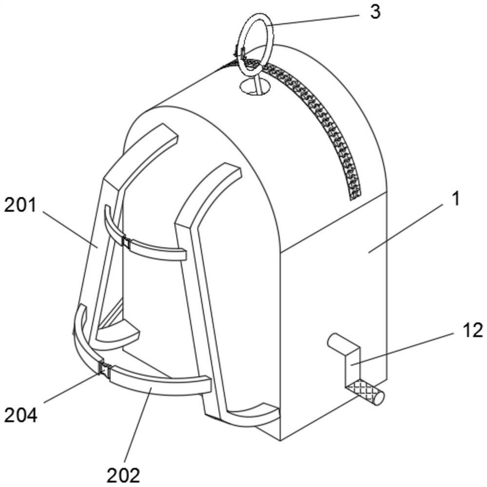
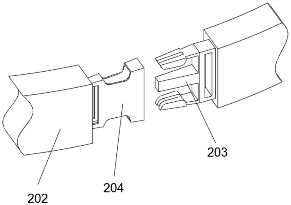
[0039] Such as Figure 1-6 As shown, the tower crane emergency escape self-rescue knapsack type slow-down device includes a knapsack main body 1, a tightening assembly 2 is provided at the rear end of the knapsack main body 1, a hanging assembly 3 is provided at the upper end of the knapsack main body 1, and a winch 4 is provided at the lower end of the knapsack main body 1. , the right end of the winch 4 is provided with a slow down assembly 5, the right end of the winch 4 is provided with a locking assembly 6, the tightening assembly 2 includes straps 201, two straps 201 are arranged in a left-right symmetrical structure, and the back of the backpack main body 1 is fixed in a vertically symmetrical structure. There are two tightening belts 202 , the middle left end of the tightening belt 202 is provided with a clip 203 , and the middle right end of the tightening belt 202 is provided with a buckle 204 .
[0040] A rope 9 is rewound on the winch 4, and the middle part of the ...
Embodiment 2
[0044] Such as Figure 7 , Figure 8 As shown, on the basis of Embodiment 1, the slow-down assembly 5 includes a notched disc 501, the rear end of the notched disc 501 is frictionally contacted with a sheave 502, the left end of the notched disc 501 is fixed with a fixed rod 503, and the upper end of the fixed rod 503 The right wall is fixed with a cylindrical pin 504, the sheave 502 is provided with radial grooves 505 in an annular array structure, the right end of the middle part of the sheave 502 is fixed with a sleeve A506, and the middle part of the sheave 502 and the sleeve A506 is fixed with a round rod 507 , the right end of the round rod 507 is slidably connected with a casing B508, and two sliding rods 509 are fixed on the casing B508 in a vertically symmetrical structure.
[0045] The cylindrical pin 504 is slidingly connected with the radial groove 505, the notch disc 501 is slidingly connected with the inner recess of the sheave 502, the right wall of the sleeve ...
Embodiment 3
[0048] Such as Figure 9 , Figure 10 As shown, on the basis of Embodiment 2, the locking assembly 6 includes a ratchet ring 601, the left wall of the ratchet ring 601 is connected and fixed to the inner right wall of the backpack main body 1, and a round block 602 is arranged inside the ratchet ring 601, and the front surface of the round block 602 is The upper end is fixed with a cylinder 603, the cylinder 603 is rotatably connected with a pawl 604, the right side of the lower end of the pawl 604 is fixed with a spring A605, the right end of the spring A605 is connected and fixed with the round block 602 through the connecting block 606, and the ratchet ring 601 rotates with the rotating shaft 10 connection, the cylinder 603 is connected and fixed to the rotating shaft 10 , and the ratchet 604 is engaged with the ratchet ring 601 .
[0049] Also includes an emergency stop assembly 11, the emergency stop assembly 11 is located at the lower right end of the backpack main body...
PUM
 Abstract
Description
Claims
Application Information
 - R&D
- Intellectual Property
- Life Sciences
- Materials
- Tech Scout
- Unparalleled Data Quality
- Higher Quality Content
- 60% Fewer Hallucinations
Browse by: Latest US Patents, China's latest patents, Technical Efficacy Thesaurus, Application Domain, Technology Topic, Popular Technical Reports.
© 2025 PatSnap. All rights reserved.Legal|Privacy policy|Modern Slavery Act Transparency Statement|Sitemap|About US| Contact US: help@patsnap.com


