Efficient energy-saving air compressor

An energy-saving, air compressor technology, used in mechanical equipment, machines/engines, liquid fuel engines, etc., can solve problems such as inability to monitor working conditions, troublesome control operations, and prone to noise.

Inactive Publication Date: 2021-09-14
泰州捷能动力科技有限公司
View PDF11 Cites 0 Cited by
  • Summary
  • Abstract
  • Description
  • Claims
  • Application Information

AI Technical Summary

Problems solved by technology

[0003] In the prior art, the patent with the authorized notification number CN202020319310.0 discloses a high-efficiency screw air compressor. Insert the oil filling pot containing lubricating oil into the inside of the oil filling nozzle and press it down, so that the top of the sealing ball can be aligned with the The bottom of the grease nozzle is detached, which is convenient for adding lubricating oil to the interior of the oil storage chamber. After the adjustment is completed, under the action of the rebound force of the return spring, the sealing ball will move upward and seal the grease nozzle, thereby preventing lubrication There will be oil leakage, and the existing air compressors have certain disadvantages when they are used. First, the bottom of the compressor is prone to moisture when in use, the shock absorption effect is poor, and noise is prone to occur, which is not conducive to people's use. Yes, it is more troublesome to disassemble and assemble the device during maintenance, the positioning effect is not good, the working status of the device cannot be monitored well, and the control operation is more troublesome, which brings certain adverse effects to people's use process. , we propose a high-efficiency and energy-saving air compressor

Method used


Image

  • Efficient energy-saving air compressor
  • Efficient energy-saving air compressor
  • Efficient energy-saving air compressor

Examples


Embodiment 1

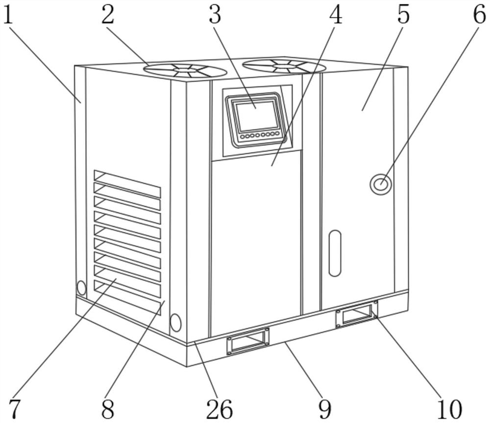
[0028] Such as Figure 1-4 As shown, a high-efficiency energy-saving air compressor includes a device main body 1, a positioning base 9 is installed on the bottom of the device main body 1, and a positioning connection seat 26 is fixedly connected between the device main body 1 and the positioning base 9. A control box 3, a motor box 4 and a compression chamber 5 are installed inside, an oil filling mechanism 6 is installed at the front end of the compression chamber 5, a cooling fan 2 is installed on the upper end of the device main body 1, and an inspection door 8 is installed outside the device main body 1.

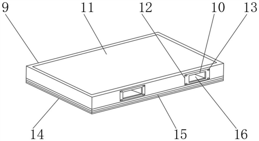
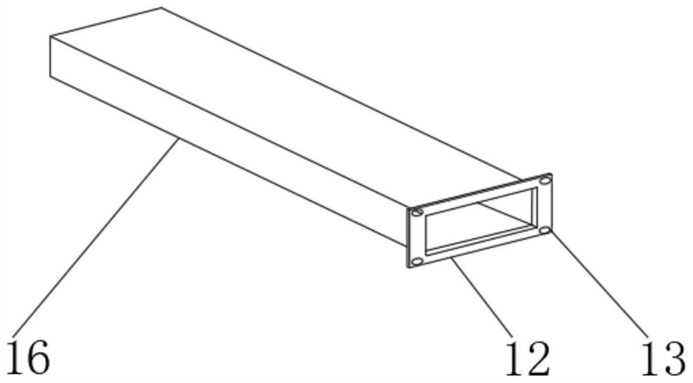
[0029] The outer surface of the upper end of the positioning base 9 is fixedly connected with a connection pad 11, the outer surface of the lower end of the positioning base 9 is fixedly connected with a shock absorber 14, the inside of the shock absorber 14 is fixedly connected with a moisture-proof bottom pad 15, and the inside of the positioning base 9 is provided with...

Embodiment 2

[0033] On the basis of Example 1, as figure 1 , 5 As shown, a high-efficiency energy-saving air compressor includes a device main body 1, a positioning base 9 is installed on the bottom of the device main body 1, and a positioning connection seat 26 is fixedly connected between the device main body 1 and the positioning base 9. A control box 3, a motor box 4 and a compression chamber 5 are installed inside, an oil filling mechanism 6 is installed at the front end of the compression chamber 5, a cooling fan 2 is installed on the upper end of the device main body 1, and an inspection door 8 is installed outside the device main body 1.

[0034] The middle part of the inspection door 8 is equipped with a cooling seat 7, and the front end of the inspection door 8 is equipped with a handle 18 and an adjustment member 20. The outer surface of the inspection door 8 is fixedly connected with a sound-absorbing pad 19, and the outer side of the inspection door 8 is provided with a chute ...

Embodiment 3

[0037] On the basis of Example 2, such as figure 1 , 6 As shown, a high-efficiency energy-saving air compressor includes a device main body 1, a positioning base 9 is installed on the bottom of the device main body 1, and a positioning connection seat 26 is fixedly connected between the device main body 1 and the positioning base 9. A control box 3, a motor box 4 and a compression chamber 5 are installed inside, an oil filling mechanism 6 is installed at the front end of the compression chamber 5, a cooling fan 2 is installed on the upper end of the device main body 1, and an inspection door 8 is installed outside the device main body 1.

[0038] The interior of the control box 3 is provided with an air monitoring sensor module, a pressure monitoring sensor module, a screw speed monitoring sensor module, an rs485 serial port communication module, a PLC intelligent control module, a power supply module, a display module and a working state control module, and an rs485 serial po...


PUM


Abstract

The invention discloses an efficient energy-saving air compressor. The efficient energy-saving air compressor comprises a device body, wherein a positioning base is installed at the bottom of the device body in a positioning mode, a positioning connecting base is fixedly connected between the device body and the positioning base, a control box, a motor box and a compression chamber are installed in the device body, an oil injection mechanism is installed at the front end of the compression chamber, a cooling fan is installed at the upper end of the device body, and an access door is installed on the outer side of the device body. The efficient energy-saving air compressor is provided with the multifunctional base, the access door convenient to disassemble and assemble and a monitoring control system, the use strength of the bottom can be improved, the effects of shock absorption and moisture prevention are achieved, the condition of bottom rotting is prevented, forking protection of a forklift is facilitated, the balance weight effect is achieved, overhauling and disassembling can be conveniently conducted, the sealing performance is excellent, the working condition in the device can be monitored conveniently, and control is facilitated.

Description

technical field [0001] The invention relates to the field of air compressors, in particular to a high-efficiency and energy-saving air compressor. Background technique [0002] The air compressor is a supporting equipment for air compression and purification. The air contains various impurities. In many industries, it is necessary to use high-purity air. The requirements for the use of air are becoming more and more stringent. Air compressors are used to provide More high-quality compressed air, with the continuous development of science and technology, people have higher and higher requirements for the manufacturing process of air compressors. [0003] In the prior art, the patent with the authorized notification number CN202020319310.0 discloses a high-efficiency screw air compressor. Insert a refueling pot containing lubricating oil into the inside of the grease nozzle and press it down, so that the top of the sealing ball can be aligned with the The bottom of the grease...

Claims


Application Information

Patent Timeline
Patent Type & Authority Applications(China)
IPC IPC(8): F04C18/16F04C23/02F04C29/00F04C29/02F04C29/04F04C29/06F04C28/00F04C28/28
CPCF04C18/16F04C18/086F04C23/02F04C29/00F04C29/02F04C29/04F04C29/06F04C28/00F04C28/28F04C2240/30
Inventor 俞扬吉任威
Owner 泰州捷能动力科技有限公司
Why Eureka
Try Eureka