Lamp heat conduction arm and heat conduction method thereof

A technology of lamps and heat conducting sheets, which is applied in lighting and heating equipment, semiconductor devices of light-emitting elements, cooling/heating devices of lighting devices, etc., which can solve the problems of space occupation, cumbersome disassembly and assembly of profile radiators, large installation positions, etc. question

Pending Publication Date: 2021-09-14
GUANGZHOU VAS LIGHTING
View PDF0 Cites 0 Cited by
  • Summary
  • Abstract
  • Description
  • Claims
  • Application Information

AI Technical Summary

Problems solved by technology

[0006] The heat dissipation method of high-power LED in the prior art mainly relies on profile radiators. The traditional profile radiators are cumbersome to disassemble and have low heat dissipation efficiency. The multi-piece heat sinks in the prior art are centered on the base and are mainly arranged The top of the seat, so it is necessary to reserve a large installation position, which takes up space

Method used


Image

  • Lamp heat conduction arm and heat conduction method thereof
  • Lamp heat conduction arm and heat conduction method thereof
  • Lamp heat conduction arm and heat conduction method thereof

Examples


Embodiment 1

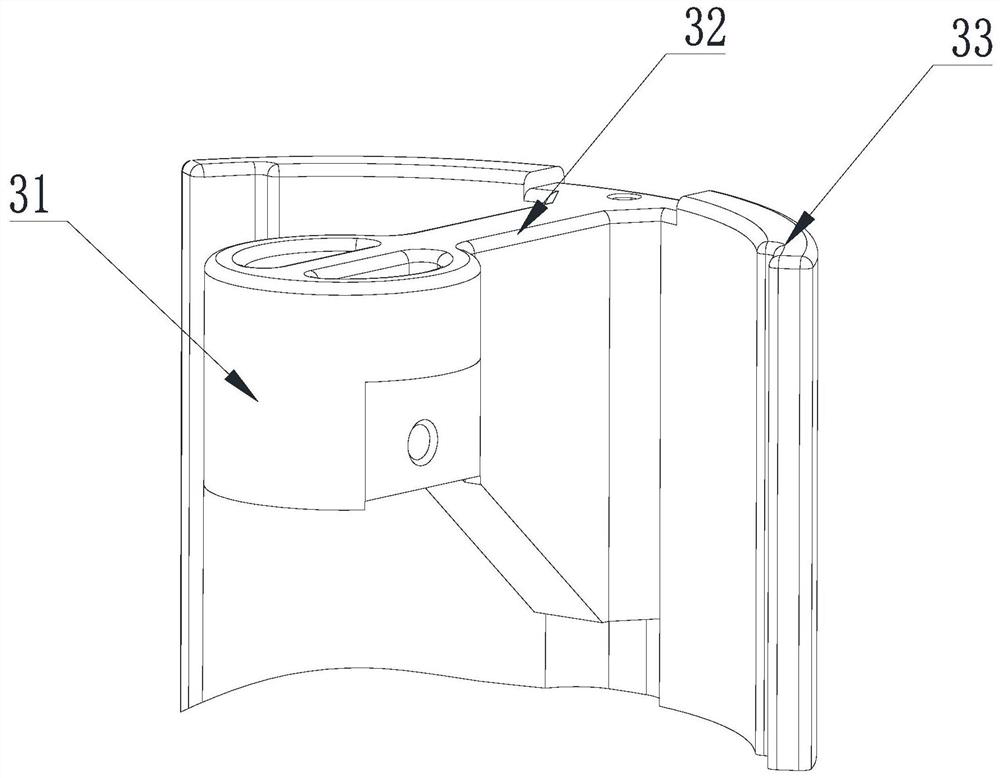
[0124] like Figure 1 ~ 2 As shown, a luminaire thermally conductive arm extends by a light source to the side surface of the lamp to achieve lateral extension heat.

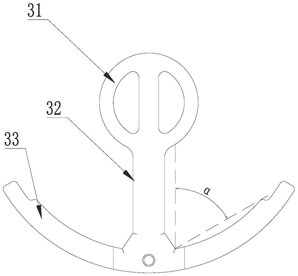
[0125] Further, the heat transfer arm 3 includes a thermally conductive end portion 31 and a thermally conductive extension portion 32 extending from the guiding end portion 31, the thermal extension portion 32 near the passage of the heat transfer end portion 31 is proximally, away from the heat conductive end portion 31 end For the distal end, the heat arm 3 further includes a heat conductive sheet 33 that extends from the distal ends of the heat transfer extension portion 32.

[0126] Further, the heat transfer sheet 33 is a circular thermally conductive sheet 33 or an arcuate thermally conductive sheet 33 or a rectangular thermally conductive sheet 33.

[0127] Further, the heat transfer end portion 31 is hollow, and one end of the heat transfer extension portion 32 extends from one side of the heat conductive end ...

Embodiment 2

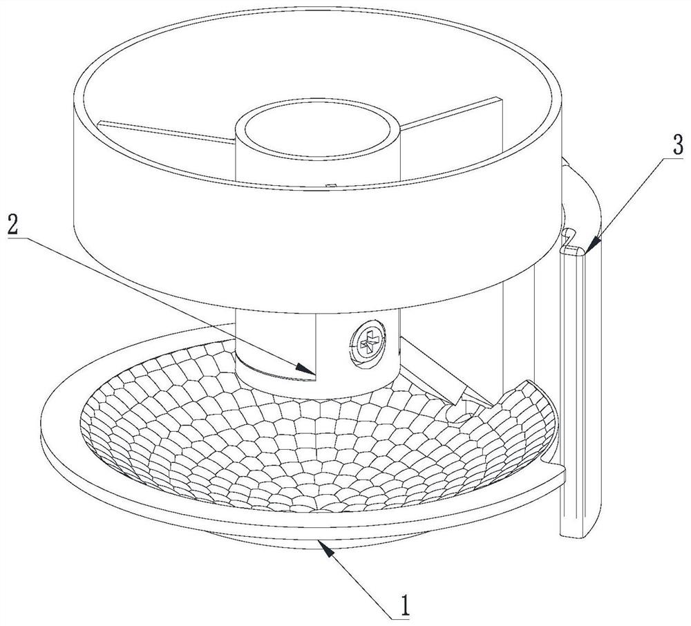
[0132] like figure 2 As shown, the present embodiment provides a mixing integrated module, including the reflector 1 and the light source assembly 2 disposed above the reflector 1, further comprising a thermally conductive arm 3 disposed over the light source assembly 2, the The heat transfer arm 3 extends laterally extending heat through the side surface of the upper direction mixing integrated module of the light source assembly 2.

[0133] Further, such as figure 1 As shown, the heat transfer arm 3 includes a thermally conductive end portion 31 that is fixedly coupled to the light source assembly 2 and a thermally conductive extension portion 32 extending from the guiding end portion 31, the heat transfer extension portion 32 adjacent to the conductive end portion 31. The proximal end, away from the heat transfer end portion 31 is the distal end, and the heat transfer arm 3 further includes a heat transfer sheet 33 extending from the distal end of the heat transfer extension po...

Embodiment 3

[0151] The present embodiment differs from the first embodiment in that, as Figure 9 As shown, the heat transfer sheet is closed, so that the heat conducting end portion is placed in a circular space.


PUM

PropertyMeasurementUnit
Angleaaaaaaaaaa
Radianaaaaaaaaaa
Thicknessaaaaaaaaaa

Abstract

The invention relates to the technical field of lamp equipment, in particular to a lamp heat conduction arm and a heat conduction method thereof. The heat conduction arm extends from a light source end to the side face of a light mixing integrated module to achieve lateral extending heat dissipation. The heat conduction method comprises the steps that heat emitted by a light source is guided out upwards, the heat continues to be conducted to the outer side of the light source, and the heat is emitted from the side face of the heat conduction arm. The lamp heat conduction arm and the heat conduction method achieve the effects that the heat dissipation speed is high, the occupied space is small, and the service life of a lamp is prolonged. The light source is reversely mounted, so that the light source is reflected multiple times, and light rays are softer. Due to the arrangement of the heat conduction arm, the mounting space of the top is saved, optical function pieces of different types can be mounted on the top of a light source module assembly to realize different optical functions, and therefore one optical integrated module can realize various different optical effects.

Description

Technical field [0001] The present invention relates to the technical field of luminaire devices, and more particularly to a lamp thermally conductive arm and a thermally conductive method thereof. Background technique [0002] The LED top lamp is a table lamp based on LED (Light Emitting Diode, "LED", LED is a solid-state semiconductor device, which can directly convert electrical conversion to light. The LED is a third-generation lighting technology after incandescent lamps and fluorescent lamps, with energy saving, environmental protection, and reliable feature. [0003] Light efficiency is an important indicator of the performance of LED lighting system. The luminous efficiency of LEDs typically decreases from about 0.2% to 1% as the temperature increases by 1 ° C. As the LED device is aging, the luminous efficiency may be higher than this data with the temperature of the temperature. In some applications, such as car headlights and compact lights, the ambient temperature aro...

Claims


Application Information

Patent Timeline
IPC IPC(8): F21V29/74F21V17/12F21V7/04F21V7/06F21V19/00F21Y115/10
CPCF21V29/74F21V17/12F21V7/04F21V7/06F21V19/001F21Y2115/10
Inventor 潘德志
Owner GUANGZHOU VAS LIGHTING
Why Eureka
Try Eureka