Front edge bending test tool and method

A bending test and leading edge technology, applied in the field of aircraft structure, can solve problems such as poor versatility, inconsistent with real working conditions, and unintuitive test results

Active Publication Date: 2021-09-14
CHINA ACAD OF AEROSPACE AERODYNAMICS
View PDF5 Cites 0 Cited by
  • Summary
  • Abstract
  • Description
  • Claims
  • Application Information

AI Technical Summary

Problems solved by technology

This method has the following disadvantages: 1) The test results are not intuitive, the test data needs to be treated equivalently, and the test phenomenon does not match the real working conditions; 2) The versatility is poor, and the fixture design needs to be redesigned for different leading edge structures

Method used


Image

  • Front edge bending test tool and method
  • Front edge bending test tool and method
  • Front edge bending test tool and method

Examples


Embodiment

[0090] 1. The design method of the leading edge bending test tooling, the steps are as follows:

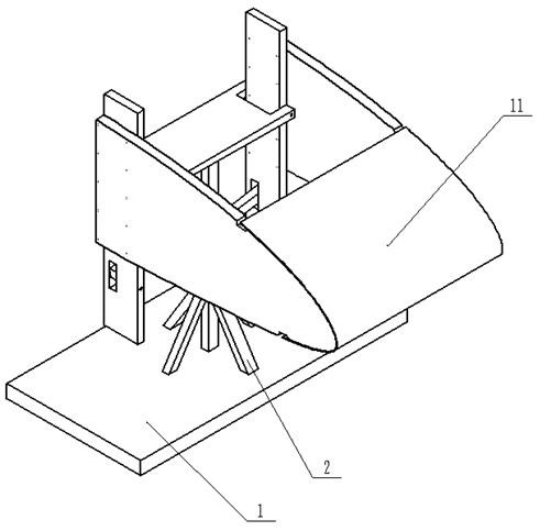
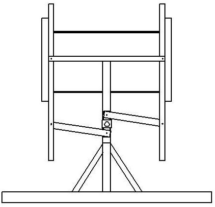
[0091] 1) Determine the shape of the ribbed plate 10 according to the cross-sectional shape of the front edge. When the front edge is a structure with a gradual change in cross-section, the shapes of the two ribbed plates 10 can be different;

[0092] 2) Determine the distance of the riser according to the length of the leading edge;

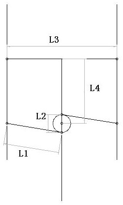
[0093] 3) According to the deformation requirements, determine the size and relative position of the long rotating rod and the short rotating rod through the calculation of the schematic diagram;

[0094] 4) Determine the torque wrench to be selected according to the size of the load, and determine the size of the hexagonal side of the loading end 7 according to the specifications of the torque wrench socket, and determine the size of the square side of the loading end 7 according to the size of the short rotating rod. It is also possible to make m...


PUM


Abstract

The invention discloses a front edge bending test tool and method. The front edge bending test tool comprises a supporting assembly, a loading end head (7), a rib type plate (10) and a bending load transmission mechanism, wherein the bending load transmission mechanism is installed on the supporting assembly, the two rib-shaped plates (10) are vertically installed on the two sides of the bending load transmission mechanism, and a front edge structure (11) to be tested is fixedly installed on front portions of the two rib-shaped plates (10); the loading end (7) is used for driving the bending load transmission mechanism to compress an upper part or a lower part of the rib-shaped plate (10), so the leading edge structure (11) to be tested is bent. According to the front edge bending test tool, the stress condition of the aircraft leading edge can be truly simulated, the bending performance of the leading edge is assessed, and safety and effectiveness of the leading edge structure are ensured.

Description

technical field [0001] The invention belongs to the technical field of aircraft structures, in particular to a leading edge bending test tool and method. Background technique [0002] The lightweight UAV uses an ultra-thin leading edge, which is connected with the wing ribs to form a complete wing segment skeleton. According to the characteristics of the airfoil of the UAV, the leading edge structure has the characteristics of large curvature and changes continuously along the direction of the wingspan. [0003] The traditional leading edge usually uses fixtures designed according to the shape of the curved surfaces at both ends, and tensile and compressive tests are performed on a tensile and compressive testing machine or through an actuator, and the bending performance of the leading edge is equivalently evaluated through tensile and compressive properties. This method has the following disadvantages: 1) The test results are not intuitive, the test data needs to be treat...

Claims


Application Information

Patent Timeline
Patent Type & Authority Applications(China)
IPC IPC(8): G01M13/00G01N3/20G01N3/02B64F5/60
CPCG01M13/00G01N3/20G01N3/02B64F5/60G01N2203/0003G01N2203/0023
Inventor 佟阳王军崔灿张凯郭懿霆
Owner CHINA ACAD OF AEROSPACE AERODYNAMICS
Why Eureka
Try Eureka