
Light-emitting tracing jumper fiber system

An electroluminescent line and fiber technology, applied in the field of fiber jumping, can solve the problems of fiber jumping trace finding relying on manual work, relying on manual tracing, and relying on management

Pending Publication Date: 2021-09-14
STATE GRID HEBEI ELECTRIC POWER CO LTD
View PDF11 Cites 0 Cited by
  • Summary
  • Abstract
  • Description
  • Claims
  • Application Information

AI Technical Summary

Problems solved by technology

The fiber jumpers in the cabinet are generally tidy, but when the fiber jumpers are placed under the anti-static floor or on the wiring bridge, it is usually necessary to bind and stack the fiber jumpers adjacent to the path, and no longer mark the fiber jumpers on the path separately mark
[0005] 2. For the situation where all kinds of fiber jumpers in the computer room are placed under the anti-static floor or on the wiring bridge, if it is necessary to operate on a specific line in the binding state, it is almost entirely dependent on manual touch-up from beginning to end. Unable to quickly and accurately locate the specified fiber jumper
Moreover, once this traditional manual maintenance encounters a large number of cables overlapping and overlapping, it will become very difficult to trace the fiber jumpers.
[0006] 3. For the labels of various fiber jumpers, the management is still completely dependent on manual work
Although the intelligent management of labels can be realized, the search for fiber patch traces still relies on manual

Method used


Image

  • Light-emitting tracing jumper fiber system
  • Light-emitting tracing jumper fiber system
  • Light-emitting tracing jumper fiber system

Examples


Embodiment Construction

[0043] In order to enable those skilled in the art to better understand the technical solution of the present disclosure, the present disclosure will be described in further detail below in conjunction with the accompanying drawings and specific embodiments.

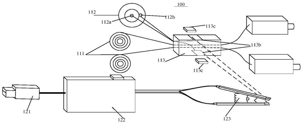
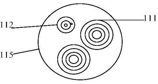
[0044] Such as Figure 1 to Figure 4 As shown, the embodiment of the present disclosure relates to a light-emitting tracing fiber jumper system 100, the light-emitting tracing fiber jumper system 100 includes a light-emitting tracing fiber jumper 110 and an AC power supply device 120, and the light-emitting tracing fiber jumper 110 includes a jumper The fiber core 111 , at least one electroluminescent wire 112 , the first connector component 113 and the second connector component 114 .

[0045] Such as figure 1 and figure 2 As shown, the electroluminescence wire 112 is arranged outside the fiber jumper core 111 . For example, the electroluminescent wire 112 may be arranged outside the fiber jumper core 111 by bonding...


PUM


Abstract

The invention provides a light-emitting tracing jumper fiber system, which comprises a light-emitting tracing jumper fiber and an alternating-current power supply device, and is characterized in that the light-emitting tracing jumper fiber comprises a jumper fiber core, at least one electroluminescent wire, a first joint assembly and a second joint assembly, the electroluminescent wire is arranged on the outer side of the jumper fiber core, the alternating-current power supply device is selectively and electrically connected with the first joint assembly and the second joint assembly so as to provide an alternating-current signal, the first joint assembly and the second joint assembly are both arranged on the jumper fiber core, the first joint assembly and the second joint assembly are electrically connected with the electroluminescent wire so as to excite the electroluminescent wire to emit light under the action of the alternating-current signal, and the electroluminescent wire is excited to emit light under the action of the alternating-current electric signal provided by the alternating-current power supply device, so that the trend trace of the jumper fiber can be conveniently and quickly searched.

Description

technical field [0001] The disclosure belongs to the technical field of fiber jumping, and in particular relates to a light-emitting tracing fiber jumping system. Background technique [0002] For the commonly used fiber jumpers used in various communication centers, data centers and other equipment rooms, most of them only have the function of equipment interconnection data transmission, and they do not have the ability to indicate the connection relationship and display the display path. [0003] Commonly used fiber jumpers refer to: [0004] 1. For the equipment and wiring system connected by fiber jumpers in the actual computer room environment, the fiber jumpers in the cabinet are usually maintained and managed by manual labeling. The fiber jumpers in the cabinet are generally tidy, but when the fiber jumpers are placed under the anti-static floor or on the wiring bridge, it is usually necessary to bind and stack the fiber jumpers adjacent to the path, and no longer ma...

Claims


Application Information

Patent Timeline
IPC IPC(8): G02B6/44H05B33/06H05B33/08H05B44/00
CPCG02B6/4471G02B6/4439H05B33/06
Inventor 尚立魏肖明张志钦王九成
Owner STATE GRID HEBEI ELECTRIC POWER CO LTD
Learn More