Non-contact rotary switch
A rotary switch, non-contact technology, applied in the field of switches, can solve problems such as broken springs, short life of rotary switches, plastic deformation, etc.
- Summary
- Abstract
- Description
- Claims
- Application Information
AI Technical Summary
Problems solved by technology
Method used
Image

Examples
Embodiment 1
[0041] Embodiment 1, with reference to figure 1 —7, it should be noted that, Image 6 Among them, "gear positioning balance position 1" and "gear positioning balance position 2" are actually the two pulse level signals of A and B when the switch shaft 3 is not turned, and "channel A" and "channel B" are the following A, B two-way pulse level number;
[0042] A non-contact rotary switch,
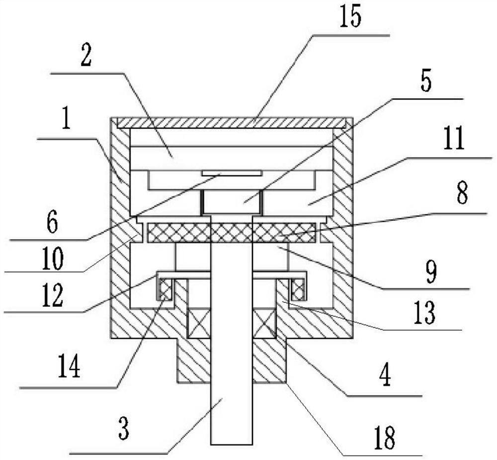
[0043] Including the outer casing 1, the outer casing 1 can be formed as a hollow cylindrical body whose cross-section is in the shape of a ring, and has,
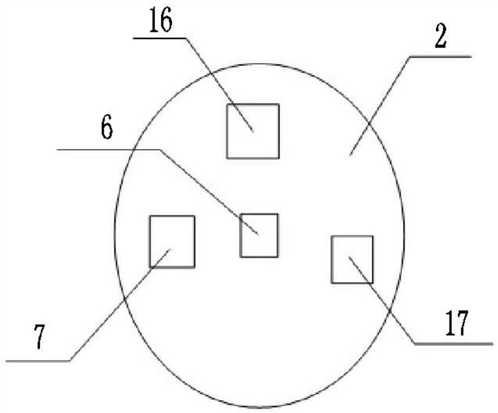
[0044] The calculation board 2, the calculation board 2 can be formed into a cylindrical structure with a circular cross section;
[0045] The switch shaft 3 that can be rotated and pressed is placed under the resolving board 2. Specifically, the bottom surface of the outer shell 1 can be formed with a hole for installing the bearing 4, and the switch shaft 3 can be installed in the outer shell 1 through the bearing 4. For example, us...
Embodiment 2
[0051] Embodiment 2, a non-contact rotary switch described in Embodiment 1, when the switch shaft 3 is rotated, the magnet located on the switch shaft 3 rotates relative to the magnetic conversion chip 6, and the magnetic conversion chip 6 located above the magnet detects After the direction of the magnetic field of the magnet changes, two sinusoidal signals V with a phase difference of 90° are output 0 Sinθ and cosine signal V 0 Cosθ, the processor 7 outputs two-way pulse level signals A and B from the sine signal and cosine signal, and defines that when the switch shaft 3 rotates clockwise, the sine signal V 0 Sinθ leading cosine signal V 0 Cosθ90°, when the switch axis 3 rotates counterclockwise, the cosine signal V 0 Cosθ leads the sinusoidal signal V 0 Sinθ90°;
[0052] When the switch shaft 3 is pressed, the distance between the magnet on the switch shaft 3 and the magnetic conversion chip 6 decreases, and the magnetic conversion chip 6 senses that the magnetic field...
Embodiment 3
[0053] Embodiment 3, a non-contact rotary switch described in Embodiment 1,
[0054] The rotation damping assembly is composed of a rotation absorbing part placed on the switch shaft 3 and magnetized according to the rotation direction of the switch shaft 3, and a rotating damping part placed in the outer shell 1 with an adsorption surface capable of generating suction with the rotating absorbing part,
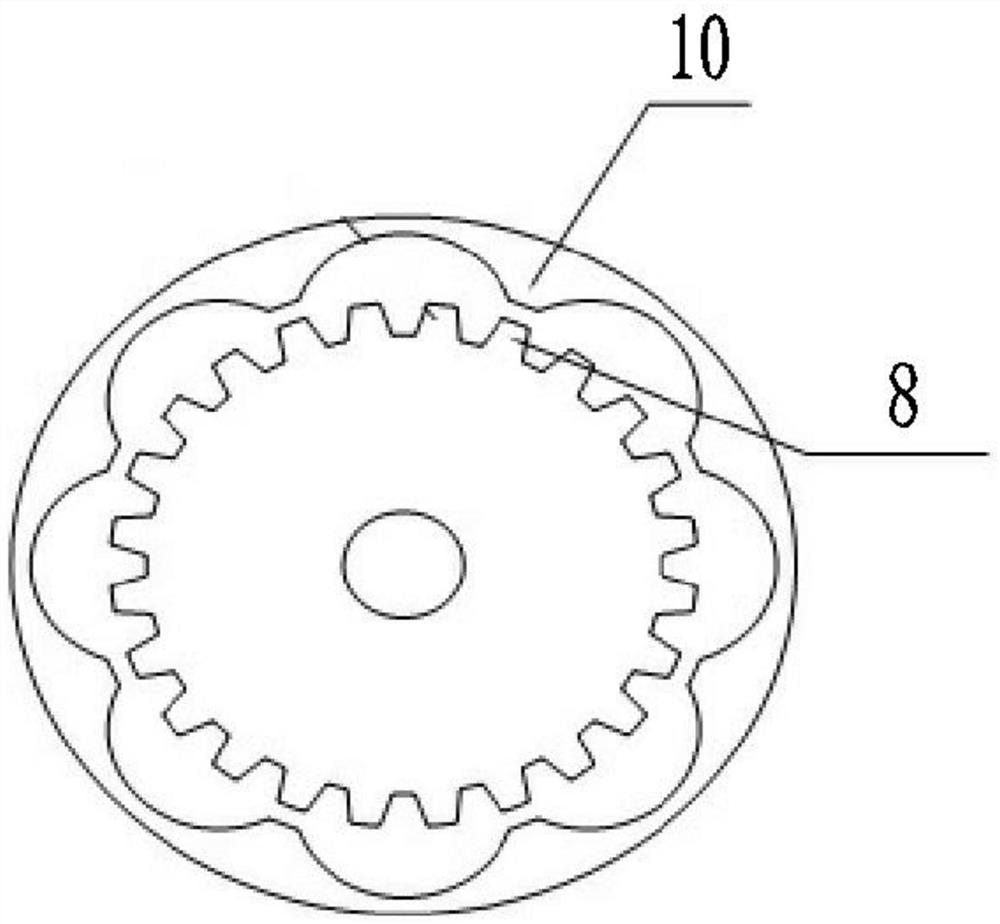
[0055] The rotary adsorption part includes a toothed disc 8 fixed on the switch shaft 3, and the toothed disc 8 is provided with a first axially magnetized magnetic ring 9 for magnetizing the toothed disc 8;
[0056] The outer shell 1 corresponding to the gear plate 8 is provided with a gear ring 10 arranged concentrically, and there is an adsorption gap between the tooth tips of the inner teeth of the gear ring 10 and the tooth tips of the outer teeth of the gear plate 8 .
[0057] In Embodiment 3, both the outer peripheral surface of the toothed disc 8 and the inner peripher...
PUM
 Abstract
Description
Claims
Application Information