Asynchronous motor structure

A technology for asynchronous motors and motor units, which is applied in the field of electric motors and can solve the problems of inconvenient replacement of a single iron core and other components, easy burning, and prone to sweeping accidents, etc.

Pending Publication Date: 2021-09-14
屈家发
View PDF7 Cites 2 Cited by
  • Summary
  • Abstract
  • Description
  • Claims
  • Application Information

AI Technical Summary

Problems solved by technology

[0003] A cooling fan must be installed during operation. Once the fan is damaged, the temperature rises rapidly and it is easy to burn out. At the same time, the rotating shaft is subjected to a large force during rotation and the temperature increases, which reduces the service life of the rotating shaft. Once the rotating shaft is damaged, cleaning accidents are likely to occur. Cause the whole machine to be scrapped
And it is also very inconvenient for the replacement of a single iron core and other parts

Method used


Image

  • Asynchronous motor structure
  • Asynchronous motor structure
  • Asynchronous motor structure

Examples


Embodiment Construction

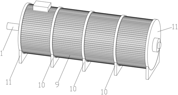
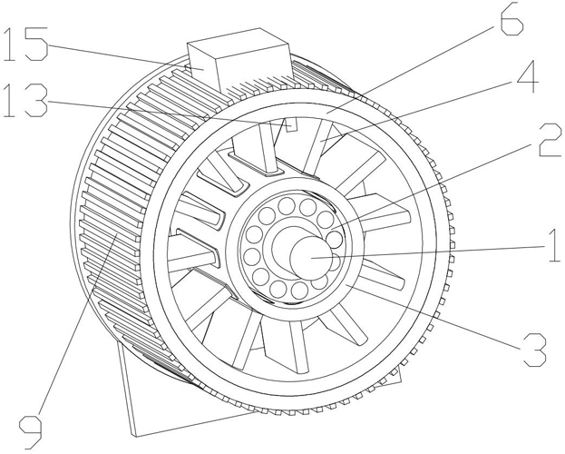
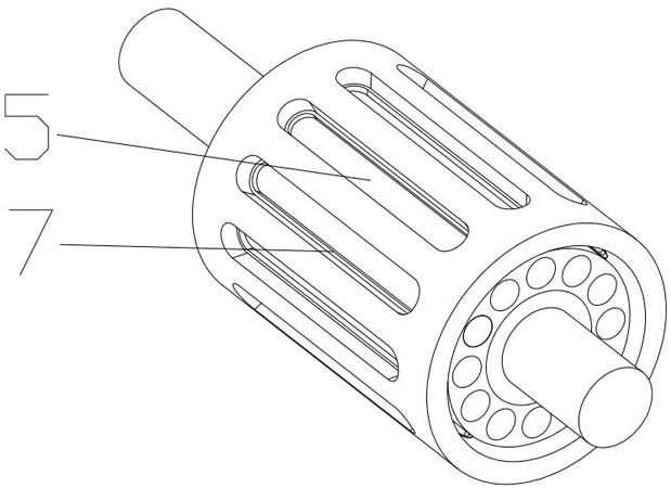
[0025] like Figure 1-5 As shown, an asynchronous motor structure includes a rotating shaft 1, on which several groups of motor units are arranged, and the motor unit includes a rotor 2 fixed on the rotating shaft 1, and an inner ring 3 is sleeved on the outer side of the rotor 2 , there is a gap between the inner ring 3 and the rotor 2; the inner ring 3 is provided with a slot 5 for inserting the silicon steel sheet 4, the outer side of the silicon steel sheet 4 is provided with an outer magnetic ring 6, the outer end of the silicon steel sheet 4 is connected The inner side walls of the magnetic ring 6 are in contact but not connected, and the silicon steel sheet 4 is wound with a coil.

[0026] Preferably, the bottom of the slot 5 is provided with a stop bar 7 , the bottom of the silicon steel sheet 4 is provided with a silicon steel sheet base 8 , and the silicon steel sheet base 8 is matched with the slot 5 . The silicon steel sheet is set in the form of insertion and pla...


PUM


Abstract

An asynchronous motor structure comprises a rotating shaft, a plurality of motor units are arranged on the rotating shaft, each motor unit comprises a rotor fixedly arranged on the rotating shaft, an inner ring is arranged on the outer side of the rotor in a sleeving mode, and a gap exists between the inner ring and the rotor; and the inner ring is provided with a slot for inserting the silicon steel sheet, the outer side of the silicon steel sheet is provided with an outer magnetic ring, the outer end of the silicon steel sheet is in contact with but not connected with the inner side wall of the outer magnetic ring, and a coil is wound outside the silicon steel sheet. According to the asynchronous motor structure provided by the invention, the structure is simplified, the power is improved, and the maintenance is convenient.

Description

technical field [0001] The invention relates to the technical field of motors, in particular to an asynchronous motor structure. Background technique [0002] The traditional motor has few windings, and the length of the winding after winding is equivalent to the length of the body, or even larger than the body, which reduces the number of winding turns and reduces the contact area between the excitation and the electromagnetic field. [0003] A cooling fan must be installed during operation. Once the fan is damaged, the temperature rises rapidly and it is easy to burn out. At the same time, the rotating shaft is subjected to a large force during rotation and the temperature increases, which reduces the service life of the rotating shaft. Once the rotating shaft is damaged, cleaning accidents are likely to occur. Cause the whole machine to be scrapped. And it is also very inconvenient for the replacement of a single iron core and other parts. Contents of the invention ...

Claims


Application Information

Patent Timeline
Patent Type & Authority Applications(China)
IPC IPC(8): H02K16/00H02K3/28H02K1/18H02K11/25H02K11/21
CPCH02K16/00H02K3/28H02K1/185H02K11/25H02K11/21
Inventor 屈家发
Owner 屈家发
Why Eureka
Try Eureka