Flame detector

A flame detector and flame radiation technology, applied in the field of flame detectors, can solve the problem that the signal is highly dependent on the operating conditions of the furnace

Inactive Publication Date: 2004-01-07
ELECTROWATT TECH INNOVATION
View PDF0 Cites 0 Cited by
  • Summary
  • Abstract
  • Description
  • Claims
  • Application Information

AI Technical Summary

Problems solved by technology

The disadvantage of these flame detectors of the latter is that their signal is highly dependent on the operating conditions of the furnace

Method used


Image

  • Flame detector
  • Flame detector
  • Flame detector

Examples


Embodiment Construction

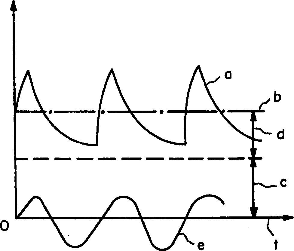
[0021] figure 1 A radiation sensor 1 ( figure 2 ) signal U 1 The time-varying curve a of , when the (first type) ignition spark generator is in operation and generates an ignition spark, and the flame has been ignited. The DC voltage portion of the entire signal is shown in curve b, which includes a portion c from the flame and a portion d from the ignition spark. Finally, the alternating frequency part from the ignition spark is shown in curve e, whose frequency coincides with the mains frequency. The ratio of the magnitude of the alternating voltage part (curve e) to the magnitude of the direct voltage part (part d) is different for different types of ignition spark generators. In cases where the characteristic frequency of the alternating voltage part is also different, this difference can be compensated by a suitable filter, as described below. This makes it possible to use the same flame detector for different ignition spark generators.

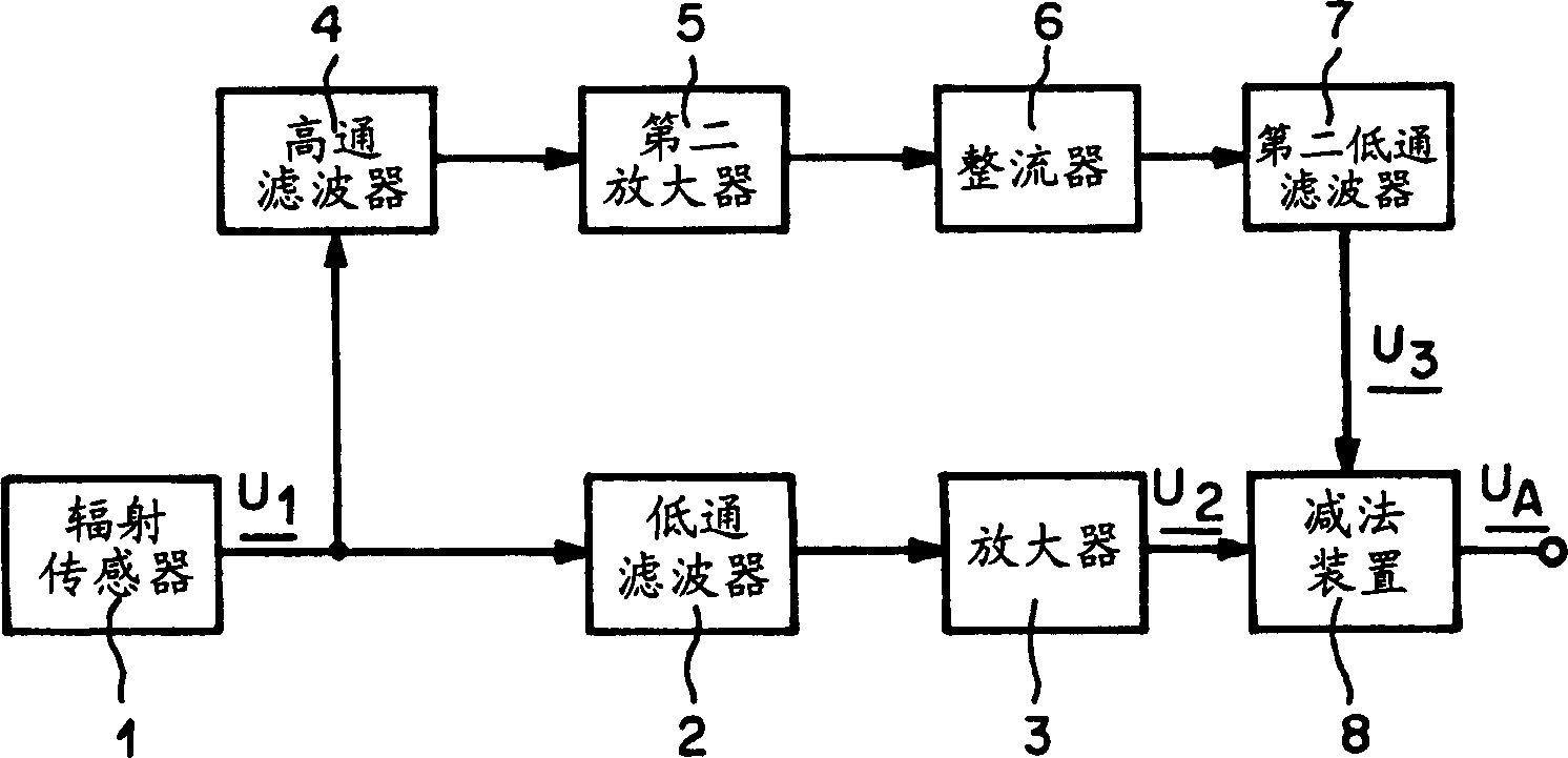
[0022] figure 2 An exampl...


PUM


Abstract

A flame detector with a radiation sensor (1) sensitive in the ultra-violet and / or visible range of the electro-magnetic spectrum, which forms from the output signal U1 of the radiation sensor, a first signal U2 which is proportional to the direct voltage portion of the signal U1, and a second signal U3 which is proportional to the alternating voltage portion of the signal U1. The output signal UA of the flame detector is formed such that UA=U2-U3. Ignition sparks can thereby be effectively suppressed.

Description

technical field [0001] The present invention relates to flame detectors. Background technique [0002] One known flame detector has a radiation sensor sensitive to the ultraviolet and / or visible range electromagnetic spectrum. This type of flame detector is used to monitor the flame in the furnace. Their task is to recognize with as little delay as possible when the flame has gone out. Flame detectors are a key element in the furnace safety concept. In order to obtain highly reliable flame detectors and furnaces, it is necessary that the flame detector responds only to the radiation of the flame and is insensitive to parasitic influences. One source of parasitic effects is sparks that occur during ignition. [0003] Known solutions for avoiding unnecessary detection of the ignition spark are, on the one hand, optical shielding methods that prevent the radiation of the ignition spark from reaching the flame detector, and, on the other hand, due to the fact that parts of t...

Claims


Application Information

Patent Timeline
Patent Type & Authority Patents(China)
IPC IPC(8): F23N5/08
CPCF23N5/082F21S8/085F21W2131/103Y02B20/72
Inventor 雷迪沃杰·波波维克亚历山大·波查德阿德里安·弗拉纳根罗伯特·拉奇德拉根·马尼克赖诺德·F·沃尔夫芬巴特尔
Owner ELECTROWATT TECH INNOVATION
Why Eureka
Try Eureka