Grinding and removing structure and hard tissue grinding and removing drill

A grinding and part removal technology, applied in the field of medical devices, can solve the problems of difficult positioning of dental burs, easy entanglement in oral mucosa, and prolonged operation time, so as to reduce the risk of surgical complications, simplify the operation, reduce the The effect of surgical difficulty

Inactive Publication Date: 2021-09-17
SHANGHAI NINTH PEOPLES HOSPITAL SHANGHAI JIAO TONG UNIV SCHOOL OF MEDICINE
View PDF10 Cites 0 Cited by
  • Summary
  • Abstract
  • Description
  • Claims
  • Application Information

AI Technical Summary

Problems solved by technology

[0004] When cutting teeth, the working edge of the dental bur is not easy to position at the initial stage, it is easy to slip, and the long exposed part is easy to get involved in the oral mucosa, which not only affects the work efficiency but also causes damage to the patient's oral cavity;
[0005] Moreover, the diameters of the existing dental burs are all the same. Although the dental burs are tapered, the diameter of the dental burs is usually thinner for cutting efficiency, so the taper is not large, resulting in small gaps formed by cutting. teeth that are difficult to remove
And in order to increase the gap, it is necessary to cut the side wall of the tooth again, so that the operation time is prolonged and the work efficiency is not good;
[0006] At the same time, when the longer working edge is cutting deep in the tooth, due to insufficient taper, the working edge is easy to get stuck in the deep part of the tooth when cutting and swinging. What's more, there will be a risk of breaking the working edge, which is also harmful to the extraction of impacted teeth. Efficiency makes a difference

Method used


Image

  • Grinding and removing structure and hard tissue grinding and removing drill
  • Grinding and removing structure and hard tissue grinding and removing drill

Examples


Embodiment Construction

[0028] The technical solutions in the embodiments of the present invention will be clearly and completely described below in conjunction with the accompanying drawings in the embodiments of the present invention. Obviously, the described embodiments are only part of the embodiments of the present invention, not all of them. Based on the embodiments of the present invention, all other embodiments obtained by persons of ordinary skill in the art without making creative efforts all belong to the protection scope of the present invention.

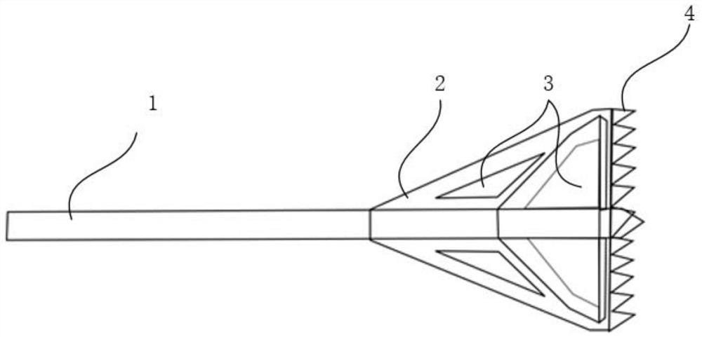
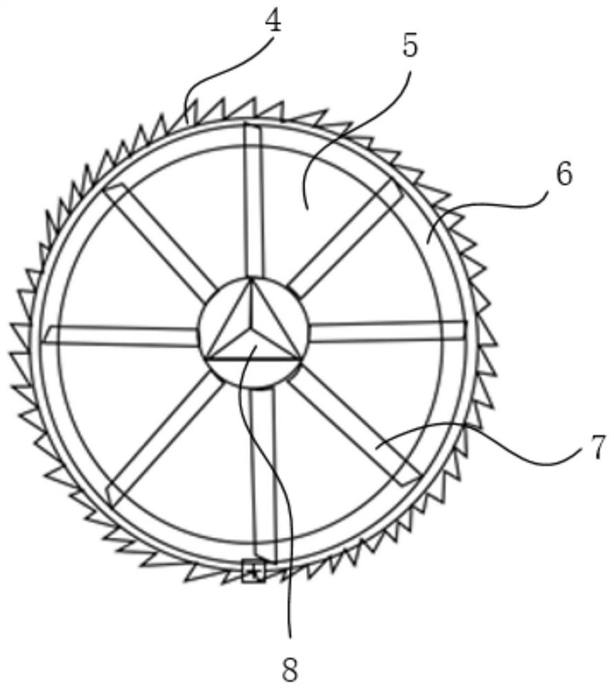
[0029] see figure 1 and figure 2 As shown, the present embodiment provides a grinding structure, including a grinding part 7 and a positioning part.

[0030] Wherein, the grinding part 7 is used for grinding away the object to be treated, such as hard tissue, which is a tissue formed by biomineralization in the living body, such as bones and teeth.

[0031] In some embodiments, the grinding part 7 is a split structure, see figure 1 and fi...


PUM


Abstract

The invention provides a grinding and removing structure and a hard tissue grinding and removing drill, the grinding and removing structure comprises a grinding and removing part and a positioning part, the grinding and removing part is used for grinding and removing an acted object, and the positioning part is arranged at the bottom of the grinding and removing structure and used for positioning the grinding and removing part on the acted object to prevent slipping. Therefore, in a dental operation, the grinding part can be driven to rotate so as to grind hard tissues, and the operation mode that in the prior art, the tooth main body is directly cut through a dental bur, and then each divided part is straightened out through a dental elevator is changed; the invention solves the problems that an existing dental bur is not easy to position during use, a gap formed by cutting is small, and the existing dental bur is easily clamped into hard tissue and even broken, is beneficial to improving the operation efficiency of a dental surgery, and reduces damage to non-grinding parts such as oral soft tissue; the invention is particularly suitable for impacted tooth extraction operation, the efficiency of tooth extraction operation is guaranteed, the operation is easier, and the risk of operative complications is reduced.

Description

technical field [0001] The invention relates to the technical field of medical devices, in particular to a grinding structure and a hard tissue grinding drill. Background technique [0002] The extraction of impacted teeth is a difficult point in tooth extraction. During extraction, the dental handpiece is usually used to drive the dental bur to rotate to perform bone removal and tooth segmentation. After the resistance is removed, the segmented teeth are then lifted out with dental elevators. Among them, the dental bur is a dental consumable assembled on the dental handpiece, which includes a working blade and a handle, the working blade is used to realize operations such as cutting teeth, and the handle is used to assemble with the dental handpiece , so that the dental bur can rotate under the drive of the dental handpiece. [0003] At present, the existing dental burs used for the extraction of impacted teeth have the following problems: [0004] When cutting teeth, the...

Claims


Application Information

Patent Timeline
Patent Type & Authority Applications(China)
IPC IPC(8): A61C3/02A61C3/025A61C3/06
CPCA61C3/02A61C3/025A61C3/06
Inventor 吴轶群孙媛元张志愿
Owner SHANGHAI NINTH PEOPLES HOSPITAL SHANGHAI JIAO TONG UNIV SCHOOL OF MEDICINE
Why Eureka
Try Eureka