Energy-saving demister for boiler desulfurization tower

A desulfurization tower and energy-saving technology, which is applied in the field of energy-saving boiler desulfurization tower mist eliminators, can solve the problems of water splashing from the top of the desulfurization tower and the reduction of the amount of mist removal, and achieve a good effect of mist removal.

Inactive Publication Date: 2021-09-17
陈旭
View PDF0 Cites 0 Cited by
  • Summary
  • Abstract
  • Description
  • Claims
  • Application Information

AI Technical Summary

Problems solved by technology

[0004] The purpose of the present invention is to provide an energy-saving boiler desulfurization tower demister to solve the problem that during the demisting process of the flue gas, due to the dilution of the flue gas by water during the spraying process, when the flue gas enters the demister, The flue gas carries a large amount of moisture and tiny particles. During the process of defogging, water droplets and ti

Method used


Image

  • Energy-saving demister for boiler desulfurization tower
  • Energy-saving demister for boiler desulfurization tower
  • Energy-saving demister for boiler desulfurization tower

Examples


Example Embodiment

[0030] Example 1:

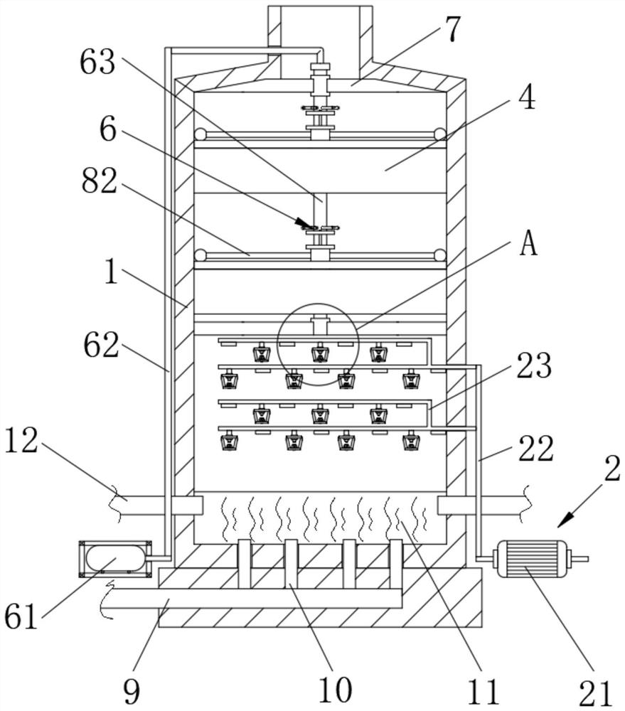
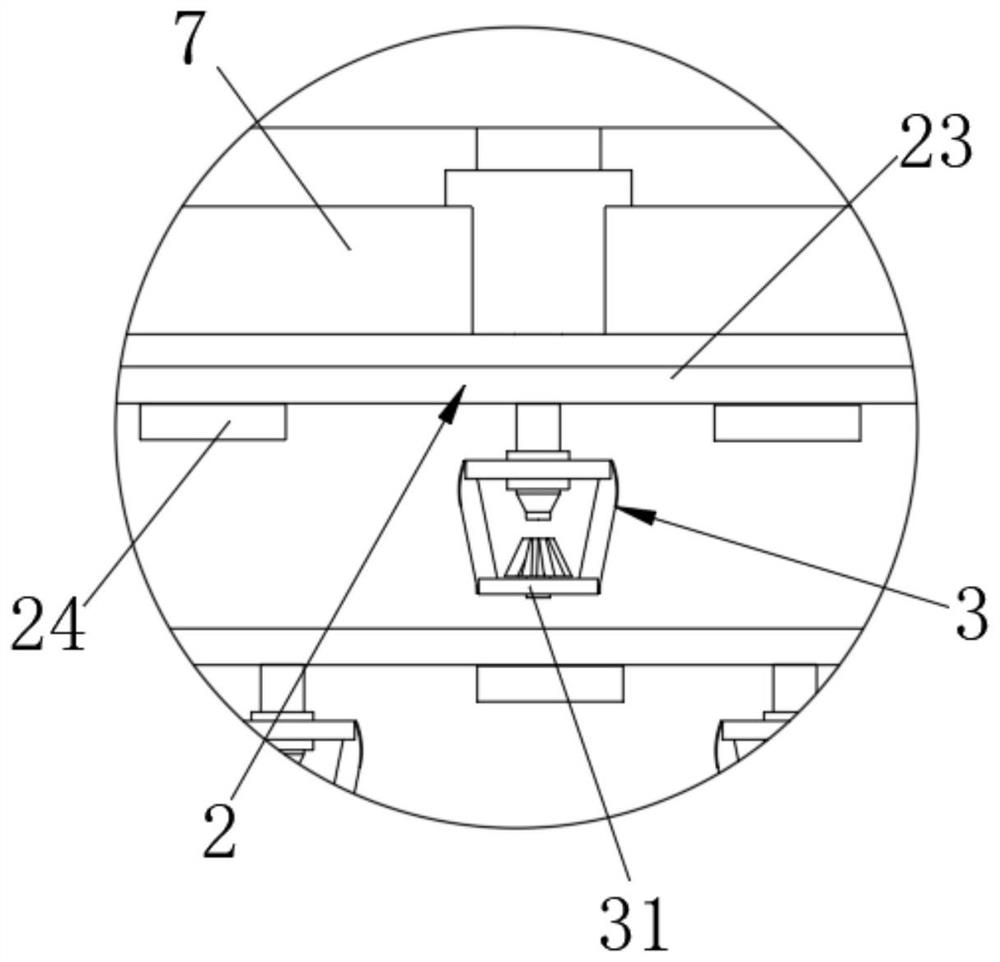
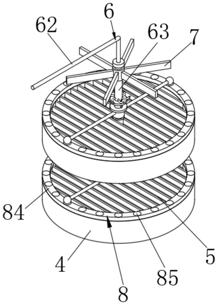
[0031] Figure 1-7 The energy-saving boiler desulfurization tower of the present invention includes a desulfurization tower body 1: a bottom portion of the dethylstada body 1, a water supply assembly 2, a bottom arrangement of the dethylstada body 1 lumen There are a plurality of injection assemblies 3, and the top and bottom of the desulfurized Tower body 1 have a fixed sleeve 4, and the inner cavity of the fixed sleeve 4 is mounted with a wave blade group 5, and the inner cavity of the desulfurized Tower body 1 is provided with a pneumatic assembly. 6, the top of the fixing sleeve 4 is provided with a hitting assembly 8, and the bottom of the left side of the desulfurized Tower body 1 is provided with a flue gas pipe 9, and the right end of the flue gas pipe 9 penetrates to the interior of the desulfurization Tower 1 and communicates with four. A gas discharge tube 10, the top end of the distribution discharge tube 10 penetrates to the inner cavity of the des...

Example Embodiment

[0034] Example 2:

[0035] Figure 1-7The energy-saving boiler desulfurization tower of the present invention includes a desulfurization tower body 1: a bottom portion of the dethylstada body 1, a water supply assembly 2, a bottom arrangement of the dethylstada body 1 lumen There are a plurality of injection assemblies 3, and the top and bottom of the desulfurized Tower body 1 have a fixed sleeve 4, and the inner cavity of the fixed sleeve 4 is mounted with a wave blade group 5, and the inner cavity of the desulfurized Tower body 1 is provided with a pneumatic assembly. 6, the top of the fixing sleeve 4 is provided with a hitting assembly 8, and the bottom of the left side of the desulfurized Tower body 1 is provided with a flue gas pipe 9, and the right end of the flue gas pipe 9 penetrates to the interior of the desulfurization Tower 1 and communicates with four. A gas discharge tube 10, the top end of the distribution discharge tube 10 penetrates to the inner cavity of the desu...


PUM


Abstract

The invention discloses an energy-saving demister for boiler desulfurization tower. The energy-saving demister comprises a desulfurization tower body, wherein a water supply assembly is arranged at the bottom of the right side of the desulfurization tower body, a plurality of spraying assemblies are arranged at the bottom of an inner cavity of the desulfurization tower body, fixing sleeves are installed at the top and the bottom of the inner cavity of the desulfurization tower body correspondingly, wave-shaped blade sets are installed in the inner cavities of the fixing sleeves, a pneumatic assembly is arranged in the inner cavity of the desulfurizing tower body, and a beating assembly is arranged at the top of each fixing sleeve. According to the device, through cooperative use of the water supply assembly and the spraying assemblies, flue gas is sprayed and diluted, SO2 and tiny particles in the flue gas are removed, then demisting is reduced under cooperative use of the fixing sleeves and the wave-shaped blade sets, and in a demisting process, demisting effect is enhanced and the inner part of a demisting plate is prevented from being blocked through cooperative use of the pneumatic assembly and the beating assemblies, so the aims of good demisting effect, thorough water removal and blockage prevention can be achieved.

Description

technical field [0001] The invention belongs to the technical field of desulfurization tower demisters, and in particular relates to an energy-saving boiler desulfurization tower demister. Background technique [0002] The demister is mainly composed of corrugated blades, plates, clips and other fixed devices. During the operation of the wet desulfurization and absorption tower, it is easy to generate "fog" with a particle size of 10-60 microns. "Fog" is not only Contains water, it also dissolves sulfuric acid, sulfate, sulfur dioxide, etc., and also causes contamination and serious corrosion of fans, heat exchangers and flue ducts. Therefore, the wet desulfurization process requires demisting of the absorption equipment and is purified The gas is demisted before leaving the absorber. [0003] During the demisting process of the flue gas, because the flue gas is diluted by water during the spraying process, when the flue gas enters the demister, the flue gas carries a large...

Claims


Application Information

Patent Timeline
IPC IPC(8): B01D53/50B01D50/00B01D53/78
CPCB01D53/504B01D2258/0283
Inventor 陈旭吕文光郑清华
Owner 陈旭
Why Eureka
Try Eureka