
Forging stock clamping and releasing manipulator for stamping steel balls

A technology of manipulator and forging blank, applied in the field of forging blank clamping and releasing manipulator, can solve the problems of increasing steel ball stamping and forming machines, large movement range of motion space, unreasonable design, etc., and achieves simplified structure, motion space and motion range. The effect of reducing and increasing the speed of grip and release

Inactive Publication Date: 2021-09-17
CHANGSHU FEIFAN METALWORK
View PDF12 Cites 0 Cited by
  • Summary
  • Abstract
  • Description
  • Claims
  • Application Information

AI Technical Summary

Problems solved by technology

[0004] The earlier forging billet conveying device for stamping steel balls was driven by a servo motor to drive a screw (that is, a "screw"), and the screw drove a sliding table to move between the aforementioned two stations. Slow, so it cannot adapt to the high-speed steel ball stamping machine, and the servo motor control system is complicated, high in cost, and expensive in daily maintenance
Although CN203109155U recommends "a device for conveying workpieces for forging presses" and CN102581197A provides "feeding manipulators for hot forging production lines", although each has the technical effects recorded in the technical effect column of the description, because they all use the aforementioned servo motor, and thus still suffers from the said lack of
[0005] The "forging material conveying device for stamping steel balls" introduced by CN108326225A makes up for the shortcomings of the aforementioned CN203109155U and CN102581197A because of abandoning the servo motor, and can objectively fulfill the advantages of the four aspects summarized in the technical effect column of the manual. However, there are still the following shortcomings: because the design of the entire structural system of the forging material clamping and placing mechanism is unreasonable, the structure is complicated on the one hand; the speed from clamping to releasing the forging blank is slow on the other hand; The lifting of the column drives the bumper to rise and fall accordingly, the bumper drives the front and rear push rods respectively, the front and rear push rods drive the front and rear clamping arms, and the front and rear clamping arms drive the front and rear splints to move to complete the clamping and releasing of the forging billet. During the clamping process of the forging billet, the movement space or range of movement of the forging billet clamping mechanism is relatively large, which increases the harsh factor to the steel ball stamping forming machine to a certain extent.

Method used


Image

  • Forging stock clamping and releasing manipulator for stamping steel balls
  • Forging stock clamping and releasing manipulator for stamping steel balls
  • Forging stock clamping and releasing manipulator for stamping steel balls

Examples


Embodiment Construction

[0017] In order to understand the technical essence and beneficial effects of the present invention more clearly, the applicant will describe in detail the following examples, but the descriptions of the examples are not intended to limit the solutions of the present invention. Equivalent transformations that are only formal but not substantive should be regarded as the scope of the technical solution of the present invention.

[0018] In the following descriptions, all concepts that may involve directionality or orientation of up, down, left, right, front and back are based on figure 1 with image 3 The current position is a reference, so it cannot be understood as a special limitation on the technical solution provided by the present invention.

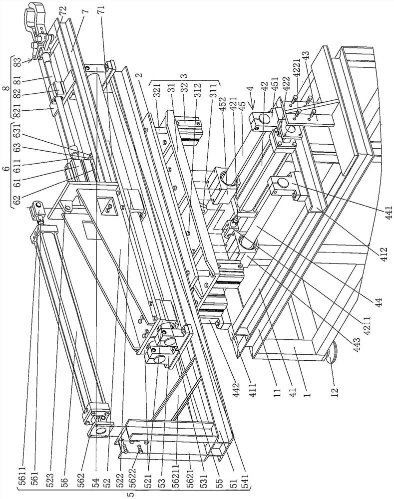
[0019] In order to facilitate the interpretation of the present invention, the applicant uses image 3 Prioritize detailed descriptions.

[0020] See image 3 , shows a frame 1, the frame 1 is a hollowed-out frame-like structure...


PUM


Abstract

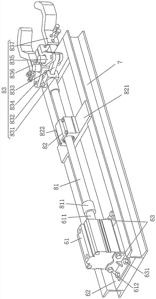
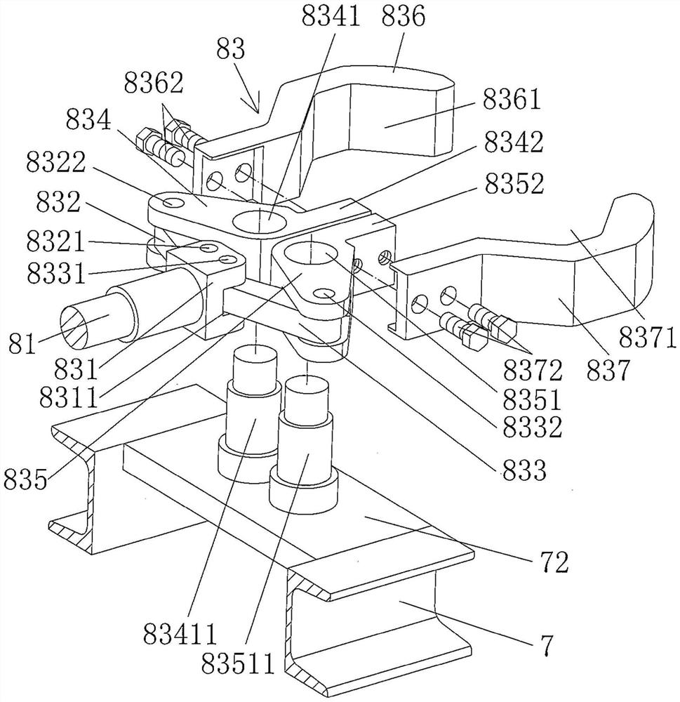
A forging stock clamping and releasing manipulator for stamping steel balls comprises a forging stock clamping and releasing manipulator opening and closing driving mechanism, a forging stock clamping and releasing mechanism support and a forging stock clamping and releasing mechanism; the forging stock clamping and releasing manipulator opening and closing driving mechanism is arranged at the left end of the forging stock clamping and releasing mechanism support; the right end of the forging stock clamping and releasing mechanism support is a horizontal cantilever end; the forging stock clamping and releasing mechanism comprises a forging stock clamping and releasing manipulator opening and closing pulling rod, a pulling rod guide sliding seat and a forging stock clamping and releasing manipulator; the left end of the forging stock clamping and releasing manipulator opening and closing pulling rod is connected with a forging stock clamping and releasing manipulator driving action cylinder, the middle is matched with the pulling rod guide sliding seat, the pulling rod guide sliding seat is fixed to a guide sliding seat fixing plate, the guide sliding seat fixing plate is fixed to the middle of the forging stock clamping and releasing mechanism support, the right end of the forging stock clamping and releasing manipulator opening and closing pulling rod extends to the right side of the pulling rod guide sliding seat, and the forging stock clamping and releasing manipulator is arranged on a forging stock clamping and releasing mechanism support right fixing plate in a pivoted mode. The structure is simplified, and the clamping and releasing speed for a forging stock is increased.

Description

technical field [0001] The invention belongs to the technical field of auxiliary facilities for steel ball stamping forming equipment, and in particular relates to a forging billet clamping and releasing manipulator for stamping steel balls. Background technique [0002] The aforementioned forging billet is also called bar stock or bar section (the same below). The steel ball stamping process is roughly as follows: first, the steel round bar as the raw material is introduced into the heating furnace for heating, and then the heated steel round bar is cut into forging billets according to the volume of the steel ball to be formed, and the forging billet is conveyed by the forging billet The device is sent to the steel ball stamping forming machine to be stamped and formed into steel balls. [0003] Through the above description and combined with professional knowledge, it can be determined without doubt that the forging billet conveying device and the forging billet clamping...

Claims


Application Information

Patent Timeline
Patent Type & Authority Applications(China)
IPC IPC(8): B21K27/02B21K1/02
CPCB21K27/02B21K1/02
Inventor 陈刚顾志文杨建平陆宇峰
Owner CHANGSHU FEIFAN METALWORK
Learn More