Assembling equipment for automobile mechanical water pump
A technology for mechanical water pump and assembly equipment, applied in metal processing equipment, assembly machines, metal processing and other directions, can solve the problems of pressing, difficult matching, poor consistency, etc., to achieve high efficiency, improve yield, and good performance consistency Effect
- Summary
- Abstract
- Description
- Claims
- Application Information
AI Technical Summary
Problems solved by technology
Method used
Image
Examples
Embodiment 1
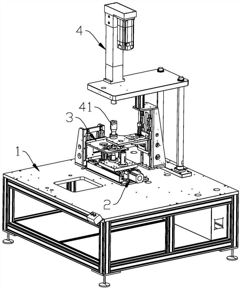
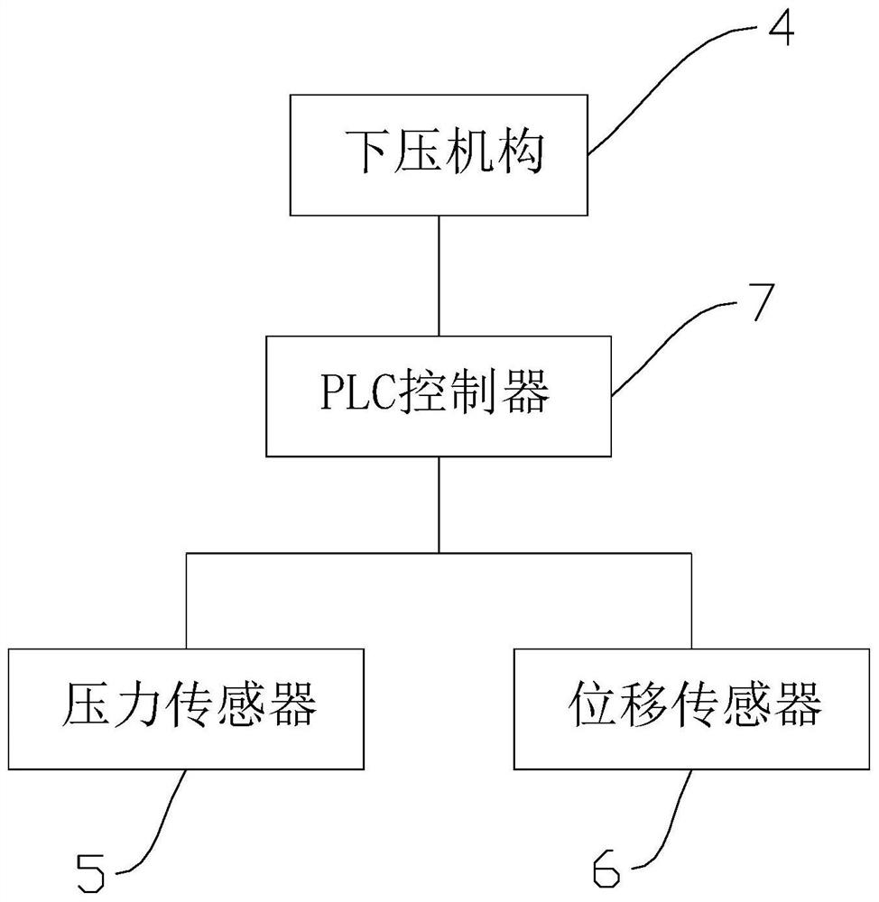
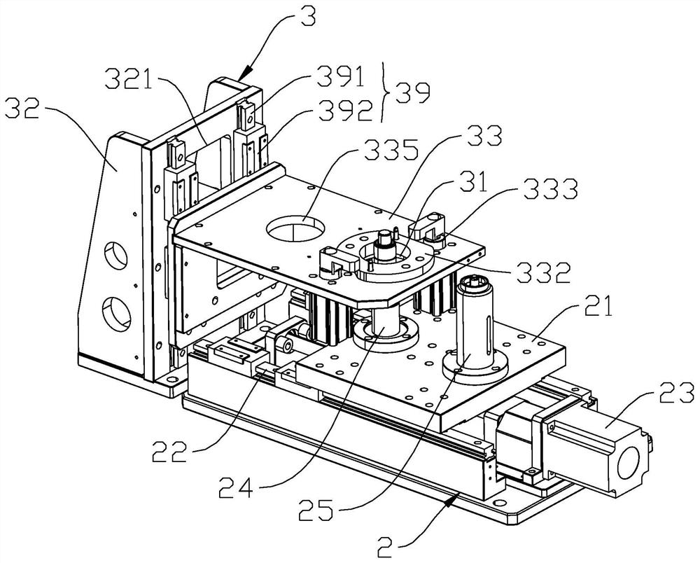
[0029] Embodiment one: if Figure 1-9 As shown, an assembly equipment for an automobile mechanical water pump includes a workbench 1, and the workbench 1 is sequentially provided with a placement and positioning mechanism 2 for vertically placing shaft-connected bearings and water seals on the workbench 1 for fixed installation. The water pump body and the water pump body fixing seat 3 which can move up and down and the pressing mechanism 4 provided with the pressure head 41, the water pump body fixing seat 3 is provided with a through hole 31 for the shaft connection bearing and the water seal to pass through, the pressure head 41, The central hole and the through hole 31 of the water pump body fixedly installed on the water pump body fixing seat 3 are arranged coaxially from top to bottom in the vertical direction, and the placement and positioning mechanism 2 can be horizontally moved and arranged on the workbench 1, and the placement and positioning The mechanism 2 is used...
Embodiment 2
[0032] Embodiment 2: The remaining parts are the same as Embodiment 1, the difference is that the water pump body fixing seat 3 includes a first mounting bracket 32, a first bottom plate 33 provided with a first guide hole 331, a first guide column 34, and a sleeve on the The compression spring 35 on the first guide column 34 and the first cylinder 36 that drives the first guide column 34 to move up and down, the first cylinder 36 is fixedly arranged on the workbench 1, and the driving rod of the first cylinder 36 passes through the first spring seat 37 Fixedly connected with the lower end of the first guide post 34, the upper end of the first guide post 34 passes through the first guide hole 331 and is connected with a first stop block 38, the first stop block 38 is used to prevent the first guide post 34 from contacting with the first guide post 34. The first base plate 33 is separated, and the compression spring 35 is compressed and arranged between the upper end surface of ...
Embodiment 3
[0036] Embodiment 3: The remaining parts are the same as Embodiment 1, the difference is that the workbench 1 is provided with a second mounting frame 81, a second bottom plate 82 with a second guide hole 821, a second guide column 83, and a The extension spring 84 on the second guide column 83 and the second cylinder 85 that drives the second guide column 83 to move up and down, the second cylinder 85 is fixedly arranged on the top of the second mounting bracket 81, and the driving rod of the second cylinder 85 passes through the second The spring seat 86 is fixedly connected with the upper end of the second guide column 83, and the lower end of the second guide column 83 passes through the second guide hole 821 and is connected with a second stopper 87, the second stopper 87 is used to prevent the second guide The column 83 is separated from the second bottom plate 82, and the tension spring 84 is stretched and arranged between the lower end surface of the second spring seat ...
PUM
 Abstract
Description
Claims
Application Information
 - R&D
- Intellectual Property
- Life Sciences
- Materials
- Tech Scout
- Unparalleled Data Quality
- Higher Quality Content
- 60% Fewer Hallucinations
Browse by: Latest US Patents, China's latest patents, Technical Efficacy Thesaurus, Application Domain, Technology Topic, Popular Technical Reports.
© 2025 PatSnap. All rights reserved.Legal|Privacy policy|Modern Slavery Act Transparency Statement|Sitemap|About US| Contact US: help@patsnap.com


