Salary bill positioning and cutting device for financial management

A technology for financial management and payroll, which is applied in the field of payroll positioning and cutting devices for financial management, can solve the problems of reducing the adjustment ability of the device, reducing the working capacity of the device, and being difficult to meet the needs of work, so as to reduce the possibility of movement and improve The effect of regulating ability and improving work ability

Pending Publication Date: 2021-09-17
河南经贸职业学院
View PDF8 Cites 1 Cited by
  • Summary
  • Abstract
  • Description
  • Claims
  • Application Information

AI Technical Summary

Problems solved by technology

[0003] The prior art has the following problems: 1. Most of the payroll positioning and cutting devices for financial management today have the problem that it is difficult to fix payrolls of different sizes and thicknesses, which leads to inconvenient positioning of the payroll and reduces the practicality of the device. 2. Most of the current financial management payroll positioning and cutting devices have the problem that it is difficult to adjust the angle of the cutting knife according to the needs, so that it is difficult to meet the needs of the work, thereby reducing the working capacity of the device; 3. Today's financial management Most of the positioning and cutting devices with payroll have the problem that it is difficult to adjust their height according to the needs, so that it is difficult to meet the needs of users, which in turn reduces the adjustment ability of the device

Method used


Image

  • Salary bill positioning and cutting device for financial management
  • Salary bill positioning and cutting device for financial management
  • Salary bill positioning and cutting device for financial management

Examples


Embodiment 1

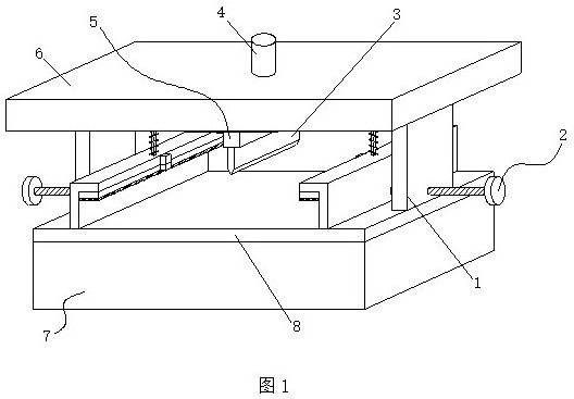
[0029] see Figure 1-6 , the present invention provides the following technical solutions: a payroll positioning and cutting device for financial management, including a workbench 8, two vertical boards 1 are installed above the workbench 8, and a top plate 6 is installed above the two vertical boards 1, A cutting knife 3 is arranged between the two vertical plates 1, an electric telescopic rod 4 is installed on the position corresponding to the cutting knife 3 on the top plate 6, and a fixing device is installed on the position corresponding to the cutting knife 3 on the vertical plate 1 2;

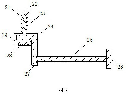
[0030] The fixing device 2 includes a screw rod 25, a first knob 26 and a moving frame 27. The two vertical plates 1 are provided with first knobs 26 on both sides away from each other, and the end of the first knob 26 close to the vertical plate 1 is equipped with a screw rod 25. The outer side of the end of the screw rod 25 away from the first knob 26 is equipped with a moving frame 2...

Embodiment 2

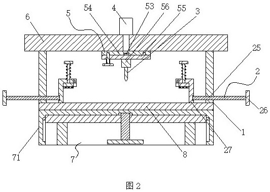
[0041] This embodiment differs from Embodiment 1 in that: the cutting knife 3 and the electric telescopic rod 4 are connected through a connection device 5, and the connection device 5 includes an insertion rod 51, a socket 52, a rotating shaft 53, a fixing plate 54, a rotating shaft Plate 55, mounting block 56, pull plate 57 and the second extension spring 58, electric telescopic link 4 is equipped with fixed plate 54 near the side of cutting knife 3, and the bottom of fixed plate 54 is equipped with rotating shaft 53 by bearing, rotating shaft 53 A rotating plate 55 is installed near the side of the cutting knife 3, and the rotating plate 55 and the cutting knife 3 are connected by a mounting block 56. A pull plate 57 is arranged below the rotating plate 55 and on the side of the mounting block 56. , an insertion rod 51 is installed above the pull plate 57, and a plurality of jacks 52 are provided on the fixed plate 54 corresponding to the insertion rod 51. There is a second...

Embodiment 3

[0047] This embodiment differs from Embodiment 1 and Embodiment 2 in that: an adjustment device 7 is installed below the workbench 8, and the adjustment device 7 includes a bottom box 71, a screw rod 72, a moving plate 73, a support plate 74 and a second knob 75, a bottom box 71 is installed below the workbench 8, a screw rod 72 is installed on the inside of the bottom box 71 through a bearing, a second knob 75 is installed below the screw rod 72, and the outside of the screw rod 72 is located on the inside of the bottom box 71 The position is installed with a moving plate 73 by threads, and a support plate 74 is installed below the moving plate 73 and on both sides of the second knob 75,

[0048] By adopting the above technical solution, the cutting device can adjust its height to a certain extent when needed, thereby facilitating the operation of different users and better meeting the needs of different users.

[0049] Furthermore, in the present invention, sliders 77 are in...


PUM


Abstract

The invention discloses a salary bill positioning and cutting device for financial management, and belongs to the technical field of financial management. The salary bill positioning and cutting device comprises a workbench. Two vertical plates are installed on the top of the workbench, a top plate is installed on the tops of the two vertical plates, and a cutter is arranged between the two vertical plates. An electric telescopic rod is installed at the position, corresponding to the cutter, of the top plate, and fixing devices are installed at the positions, corresponding to the cutter, of the vertical plates. Each fixing device comprises a threaded rod, a first rotary knob and a moving frame. The first rotary knobs are arranged on the two sides, far away from each other, of the two vertical plates, and each threaded rod is installed at the end, close to the corresponding vertical plate, of the corresponding first rotary knob. According to the salary bill positioning and cutting device, the fixing devices are arranged, and therefore the cutting device can fix salary bills with different sizes and different thicknesses when needed, positioning of the salary bills is facilitated, the possibility of movement of the salary bills is reduced, and then the practicability of the device is improved.

Description

technical field [0001] The invention belongs to the technical field of financial management, and in particular relates to a payroll positioning and cutting device for financial management. Background technique [0002] Financial management is the management of asset purchase (investment), capital financing (financing), operating cash flow (working capital), and profit distribution under a certain overall goal. Financial management is an integral part of enterprise management. It is an economic management work that organizes enterprise financial activities and handles financial relations in accordance with financial laws and regulations and the principles of financial management. [0003] The prior art has the following problems: 1. Most of the payroll positioning and cutting devices for financial management today have the problem that it is difficult to fix payrolls of different sizes and thicknesses, which leads to inconvenient positioning of the payroll and reduces the pra...

Claims


Application Information

Patent Timeline
IPC IPC(8): B26D1/08B26D5/08B26D7/02B26D7/20B26D7/26
CPCB26D1/08B26D5/086B26D7/025B26D7/2628B26D7/20
Inventor 郭彦琳李虎威
Owner 河南经贸职业学院
Why Eureka
Try Eureka