Circulating powder scattering device

A powder-spraying device and circulating conveying technology, applied in printing, rotary printing presses, printing presses, etc., can solve the problems of affecting the thermal transfer effect of images, error-prone manual duty, and low degree of automation, achieving a high degree of automation and practicality. The effect of strong and market competitiveness

Pending Publication Date: 2021-09-17
TAOTECH DIGITAL TECH
View PDF0 Cites 0 Cited by
  • Summary
  • Abstract
  • Description
  • Claims
  • Application Information

AI Technical Summary

Problems solved by technology

However, this conventional operation has the following defects: during thermal transfer, the operator needs to be on duty in real time beside the equipment, and when the powder spreading plate is about to run out of hot-melt powder, it is necessary to return the excess hot-melt powder in the powder receiving box at the bottom To the powder spreading tray, so as not to affect the whole production process due to broken powder, and manual on duty is prone to errors, and the degree of automation is low, resulting in high production costs and low production efficiency
Part of the powder spreading equipment automatically transports the hot melt powder in the bottom powder receiving box to the top powder spreading device through the screw rod, but the hot melt powder is easy to enter the bearing of the screw rod, so that the shape of the hot melt powder changes to form a block or In strip shape, the heat transfer effect of the image will be affected after the heat transfer film is adhered

Method used


Image

  • Circulating powder scattering device
  • Circulating powder scattering device
  • Circulating powder scattering device

Examples


Embodiment Construction

[0028] A further detailed description will be made below in conjunction with the accompanying drawings and embodiments of the present invention:

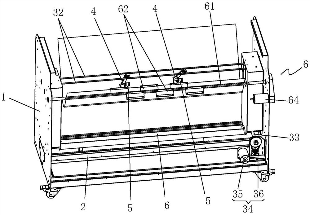
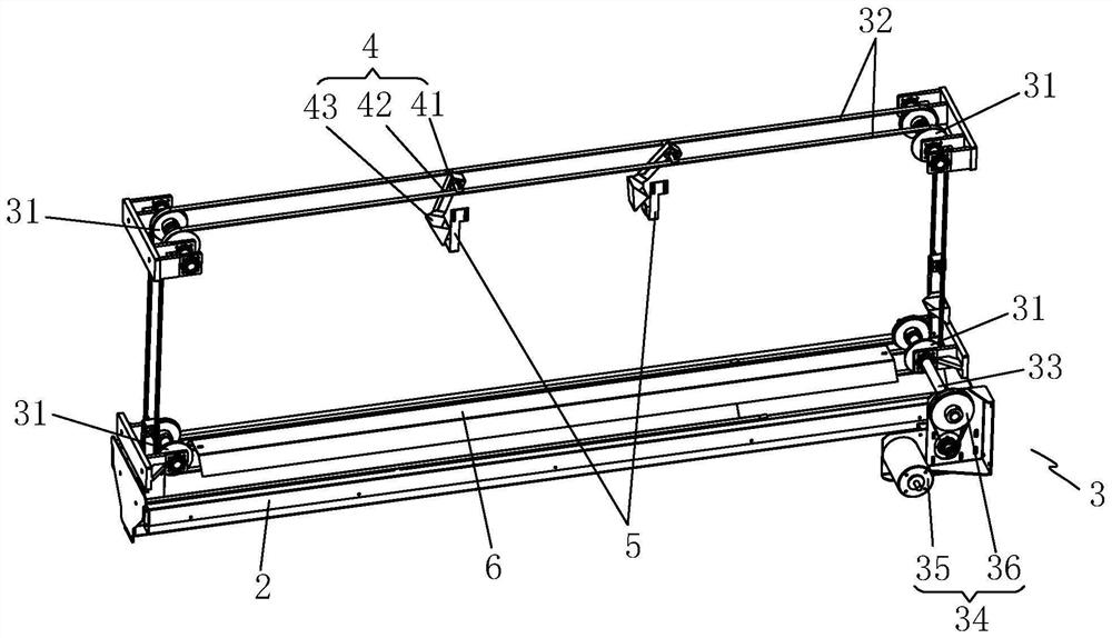
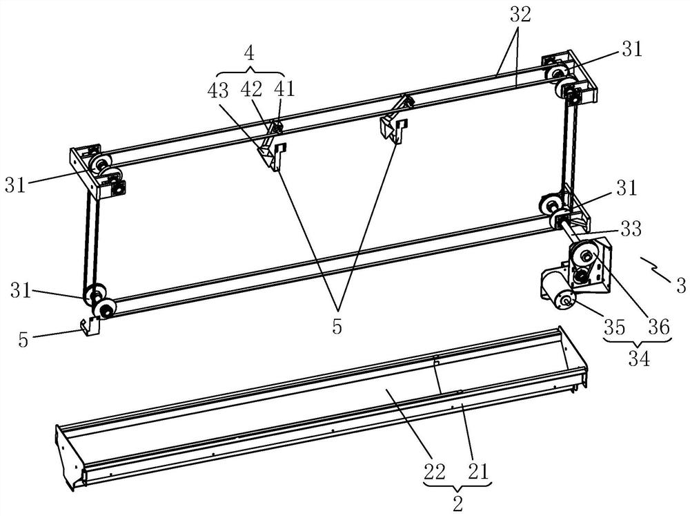
[0029] Such as Figure 1-3 As shown, a circulating powder spreading device includes a frame 1, which is provided with a powder loading mechanism 2 for loading and collecting excess hot-melt powder, a circulating conveying mechanism 3 through which thermal transfer substrates pass, At least one powder feeding mechanism 4 that moves with the circulation conveying mechanism 3 to transport the hot melt powder in the powder loading mechanism 2 to the thermal transfer substrate, and at least one is arranged above the thermal transfer substrate to tilt the powder feeding mechanism 4 A blocking mechanism 5 for sprinkling hot-melt powder on the thermal transfer substrate.

[0030] The circulation conveying mechanism 3 drives the powder feeding mechanism 4 to move. When the powder feeding mechanism 4 passes through the powder loading mechani...


PUM


Abstract

The invention discloses a circulating powder scattering device. The circulating powder scattering device comprises a rack, wherein the rack is provided with a powder loading mechanism used for loading and collecting excessive hot melt powder, a circulating conveying mechanism where a heat transfer printing substrate penetrates, at least one powder conveying mechanism which moves along with the circulating conveying mechanism and conveys the hot melt powder in the powder loading mechanism to the position above the heat transfer printing substrate, and at least one blocking mechanism arranged above the heat transfer printing substrate and used for enabling the powder conveying mechanism to incline to scatter the hot melt powder on the heat transfer printing substrate. The hot melt powder is loaded and conveyed to the heat transfer printing substrate through a hanging basket in the powder conveying mechanism, so that the situation that the hot melt powder is changed into a block shape or a strip shape due to external force can be prevented, and the quality of a heat transfer image of a product is improved.

Description

[technical field] [0001] The invention relates to a circulating powder spreading device. [Background technique] [0002] Thermal transfer printing is also called hot stamping. Thermal transfer printing generally prints the pattern on a substrate such as a thermal transfer film, then sprinkles hot melt powder on the thermal transfer film, and then removes the excess powder. Then the hot-melt powder is melted and solidified on the thermal transfer film with the pattern, so as to obtain the thermal transfer film with the pattern, and finally the pattern is transferred to the cloth by hot pressing. Thermal transfer printing has the advantages of bright colors, rich layers, low production cost, and not easy to fade. Therefore, it has broad market application scenarios. [0003] In the process of sprinkling hot melt powder, the current routine operation is to load enough hot melt powder on the powder spreader, and then shake the powder spreader intermittently, so that the powder ...

Claims


Application Information

Patent Timeline
Patent Type & Authority Applications(China)
IPC IPC(8): B41F16/00
CPCB41F16/0093
Inventor 何涛
Owner TAOTECH DIGITAL TECH
Why Eureka
Try Eureka