Energy-saving mining equipment with high dust removal efficiency

An energy-saving and high-efficiency technology, applied in the direction of earthwork drilling, cutting machinery, driving devices, etc., can solve problems such as easy dust generation, health impact of mining workers, and inability to effectively mine, so as to improve work efficiency.

Inactive Publication Date: 2021-09-17
余华东
View PDF0 Cites 0 Cited by
  • Summary
  • Abstract
  • Description
  • Claims
  • Application Information

AI Technical Summary

Problems solved by technology

[0003] In terms of mining, most existing mining machines are single-head mining, which cannot be mined well and effectively, and cannot crush the mined things in time, and cannot be transported out in time after the crushing, which affects the mining speed and the mining efficiency is low. Low, at the same time, during mining, it is easy to generate dust, which has an impact on the health of mining workers. The existing mining machines have poor dust removal effect and incomplete dust removal

Method used


Image

  • Energy-saving mining equipment with high dust removal efficiency
  • Energy-saving mining equipment with high dust removal efficiency
  • Energy-saving mining equipment with high dust removal efficiency

Examples


Embodiment 1

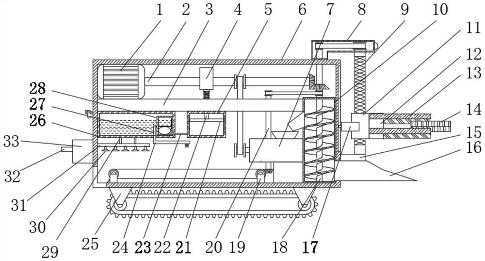
[0035] Embodiment one, such as Figure 1-7 As shown, the present invention proposes an energy-saving excavation equipment with high dust removal efficiency, comprising a first box body 6, the top of the left inner wall of the first box body 6 is welded with a first fixed plate 3, and the top of the first fixed plate 3 The first motor 1 is welded on the left side, the output end of the first motor 1 is welded with the rotating shaft 2, the outer ring of the rotating shaft 2 is welded with the eccentric wheel 4, the bottom left side of the first fixed plate 3 is welded with the water tank 26, the bottom of the water tank 26 An airbag box 28 is welded on the right side of the inner wall, and the right inner wall of the airbag box 28 is slidably connected with a blocking rod 27 that penetrates and extends to the outside of the airbag box 28. The bottom right side of the water tank 26 is sleeved with a water pipe 24, and the first fixed plate 3 The middle part of the bottom is weld...

Embodiment 2

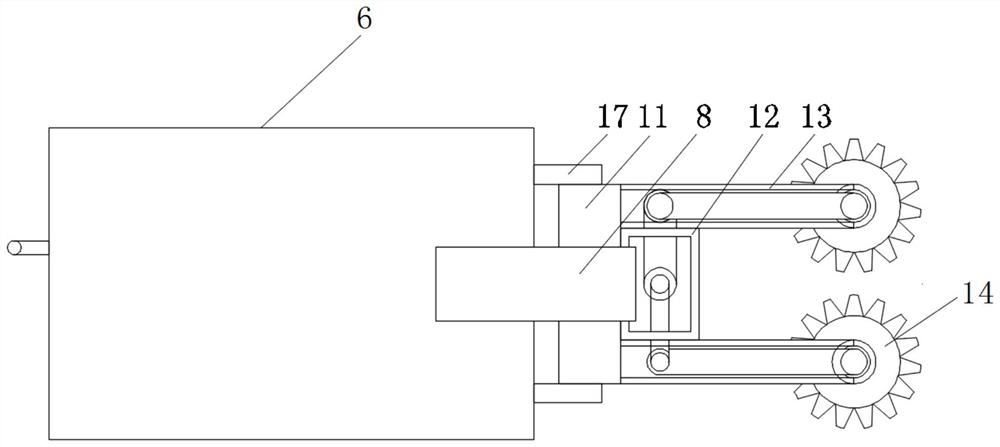
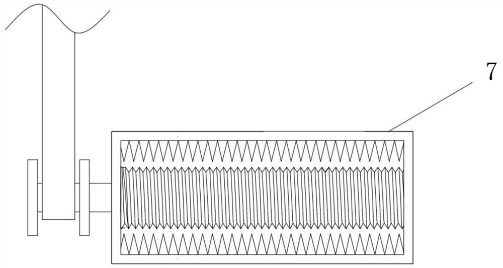
[0036] Embodiment 2, the top right side of the first box body 6 is welded with the second box body 8, the bottom inner wall right side of the first box body 6 is welded with the third box body 10, the bottom inner wall of the third box body 10 is rotatably connected with Penetrating and extending to the transmission rod 18 in the second box body 8, the left middle part of the third box body 10 is welded with a pulverizer 7, the pulverizer 7 can pulverize the mined material, and the right bottom of the third box body 10 is covered with Connected with a bucket 16 that penetrates and extends to the outside of the first box body 6, the bucket 16 is convenient for shoveling the excavated material into the third box body 10, and the top of the bucket 16 is welded with a second fixed plate 15, and the second fixed plate The top of 15 is rotatably connected with a reciprocating screw 9 that runs through and extends into the second box 8. The outer ring of the reciprocating screw 9 is s...

Embodiment 3

[0037] Embodiment 3, the bottom of the water tank is provided with a dust suction device, and the dust suction device includes an air intake pipe 31 horizontally arranged at the bottom of the water tank through a bracket 29, and a dust suction cover 30 is evenly arranged at the bottom of the air intake pipe 31, so that The left end of the air intake pipe 31 communicates with the purification box 33 arranged on the left outer wall of the first box body. A partition 37 is arranged in the middle of the interior of the purification box 33, and three sets of chutes are provided on the right side wall of the partition 37. 35, the chute 35 is slidably provided with a dust removal drawer 34, the inner wall of the dust removal drawer 34 is provided with a first filter screen 341, and a second filter screen 342 is provided below the first filter screen 341, and the dust removal drawer 34 The outer wall is provided with a handle 36, and the left side of the dividing plate 37 is provided w...


PUM


Abstract

The invention discloses energy-saving mining equipment with high dust removal efficiency, relates to the technical field of mining, and aims to solve the problems that the mining speed is influenced, the mining efficiency is low, and dust is prone to generate during mining due to the fact that most existing mining machines adopt single-head mining, cannot effectively perform mining and cannot crush mined objects in time. Aiming at the problems of influencing the health of mining workers and the like, according to the technical scheme, a dust suction device is arranged at the bottom of a water tank and comprises an air inlet pipe horizontally arranged at the bottom of the water tank through a support, dust suction hoods are evenly arranged at the bottom of the air inlet pipe, and the left end of the air inlet pipe communicates with a purifying box arranged on the outer wall of the left side of a first box body. According to the equipment, two added mining wheels can effectively perform mining, an added crushing machine can crush mined objects in time, the added water tank can achieve the dust removal effect, and the equipment is convenient to use, high in practicability and convenient to popularize.

Description

technical field [0001] The invention relates to the technical field of excavation, in particular to an energy-saving excavation equipment with high dust removal efficiency. Background technique [0002] A mining machine is a machine used for mining. It is mainly divided into an open type mining machine and a shield type mining machine. It is mainly composed of a walking mechanism, a working mechanism, a shipping mechanism and a reloading mechanism. The head is continuously mined and the mined things are transported away. It has the advantages of safety, high efficiency and high work efficiency, and is widely used in mining. [0003] In terms of mining, most existing mining machines are single-head mining, which cannot be mined well and effectively, and cannot crush the mined things in time, and cannot be transported out in time after the crushing, which affects the mining speed and the mining efficiency is low. Low, at the same time, when mining, it is easy to generate dust...

Claims


Application Information

Patent Timeline
Patent Type & Authority Applications(China)
IPC IPC(8): E21C25/18E21C31/02E21C35/00E21C35/20E21C35/22E21F13/00E21F13/06B01D46/12B02C21/02
CPCE21C25/18E21C31/02E21C35/00E21C35/20E21C35/22B02C21/026B01D46/12E21F13/002E21F13/06
Inventor 余华东
Owner 余华东
Why Eureka
Try Eureka